76
Galaxy 2 Series Installation Manual
Option 53 - Outputs
This option allows the operation of all the system outputs to be programmed. Outputs numbered 0001 to
0008 are the outputs from the trigger header. Outputs numbered 1001 to 1004 are the standard outputs on
the main PCB. Outputs on expansion modules are shown if fitted. Each output has a sub menu containing
attributes as shown:
1. Function
Assigns the output function that activates the output.
2. Polarity
This selects if the output is normally off (positive) or normally on (negative). Positive means that the output
is 12V going to 0V when activated. Negative means that the output is 0V going to 12V when activated.
3. Groups
For output types where groups are programmable, this selects the groups that an output responds to. An
output can respond to 1, 2, 3 or 4 groups.
NOTE: Reflex means that the output stays on until the condition clears.
Latch means that the output stays on until a valid user logs on (PIN or card).
Latch* means that these outputs are latched but can be forced off by bell delay, bell time or confirm
timeouts.
Pulse means that the output stays on for five seconds and then switches off again.
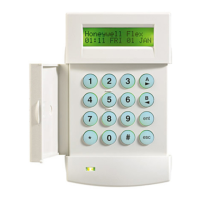
Selecting Outputs
On entering the option, the first output on the system is displayed; the output address, function and mode are
displayed on the top line, the polarity and assigned groups are displayed on the bottom line.
From the display of the first output, any output on the system can be displayed by pressing the A or B keys or
by entering the address of a specific output.
The output is selected for programming by pressing the ent key; the first output programming attribute
1= Function is displayed.
01 Bell (Latch)
The Bells output is activated on a full alarm event when the system is set. This output is subject to the Bell
Time and Bell Delay parameters.
02 Strobe (Latch)
The Strobe output is activated on a full alarm event during the set state. This output is subject to the Bell
Delay. The Strobe output follows the Bell Time, but latches on after the last rearm.
03 Panic (Latch)
The PA output is activated whenever any of the PA zone types activate. It latches on and remains active until a
valid code, with the appropriate reset level, is entered.
04 Intruder (Latch)
The Intruder output is activated on a full alarm event during the set state.
53 - Outputs

 Loading...