16
Galaxy 2 Series Installation Manual
Outputs
The Galaxy 2 Series has four on-board outputs; Bells, Strobe, Speaker and Set. The format of the address-
ing of the outputs is similar to zones. The addresses of these outputs are as follows:
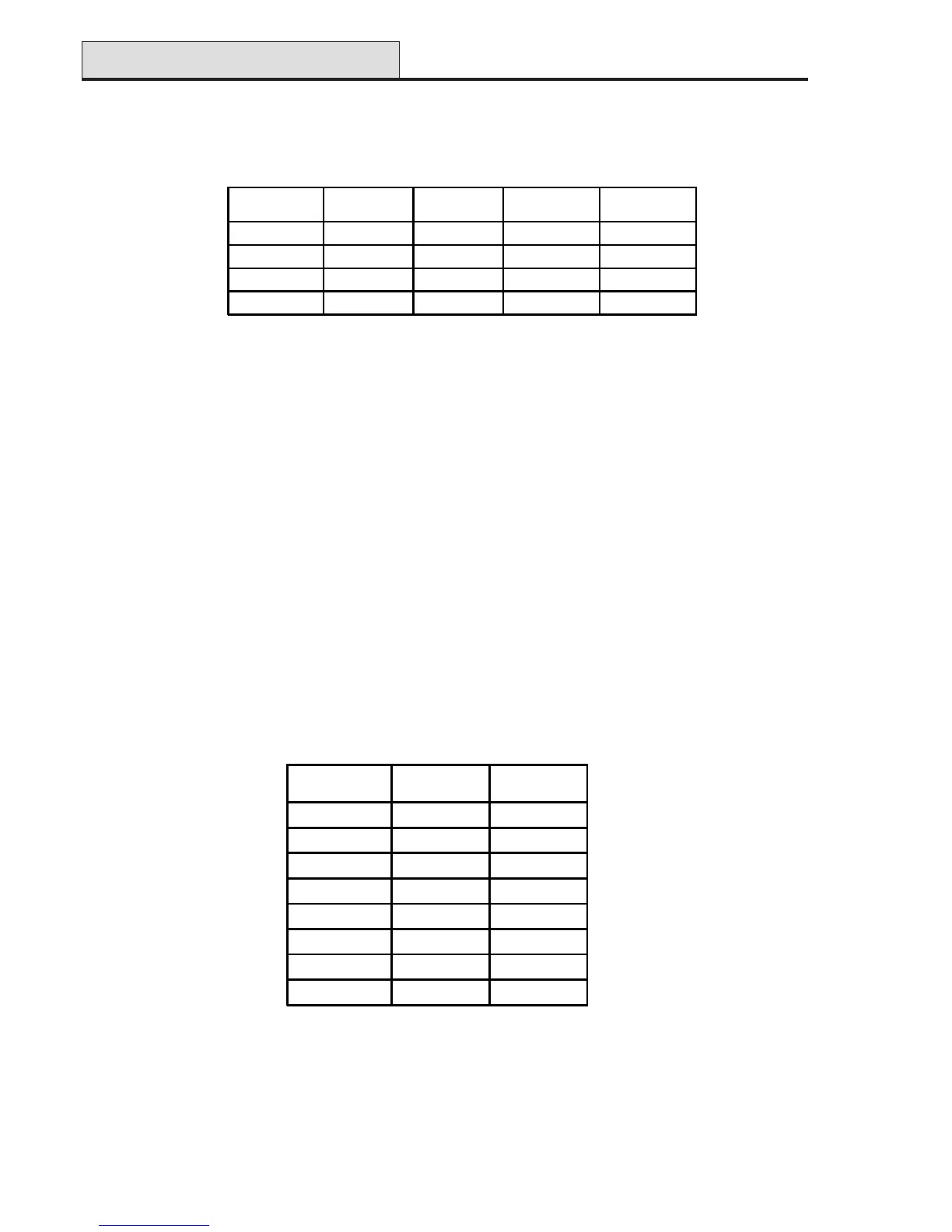
Table 3. Output Addresses
Output Addresses
Table 4. Trigger Output Addresses
*NOTE: Output 1002 - This output is configured as a 16 Ohm speaker driver (AC signal). The speaker
should be connected between this output and +12V. The speaker Entry/Exit volume is controlled
by parameter 51.10. It is possible to reprogram the output to operate as a normal switched
negative output by programming parameter 51.15 to 0=Switch DC. However, when it is repro
grammed to operate as Switch DC, a loudspeaker should never be connected directly to this
terminal otherwise damage may result. Always ensure that this parameter is set to 1=Speaker
Driver, before connecting a loudspeaker.
Trigger Header
The Trigger Header on the Galaxy 2 Series is a set of pins, which consists of programmable outputs for an
external communication module. The connection is via an optional ribbon cable (Part No. A229).
Trig 1-8
There are eight trigger outputs, which are intended as communication triggers, but can be used for any pur-
pose. By default these outputs are programmed as positive. They are designed to sink current (to 0V) not
source current (from 12V). The addresses of these outputs are as follows:
Output
Address
Default
function
Current (mA)
0001 Fire 100
0002 Panic 100
0003 Intruder 100
0004 Set 100
0005 Omit 100
0006 Not Used 100
0007 Confirm 100
0008 Not Used 100
The function of the trigger outputs can be programmed in menu 53=Outputs.
Output
Address
Default
function
Current (mA) Normal State Active State
1001 Set 100 Off 0V
1002
*
Not Used - - -
1003 Bell 100 Off 0V
1004 Strobe 100 Off 0V

 Loading...