19
Galaxy 2 Series Installation Manual
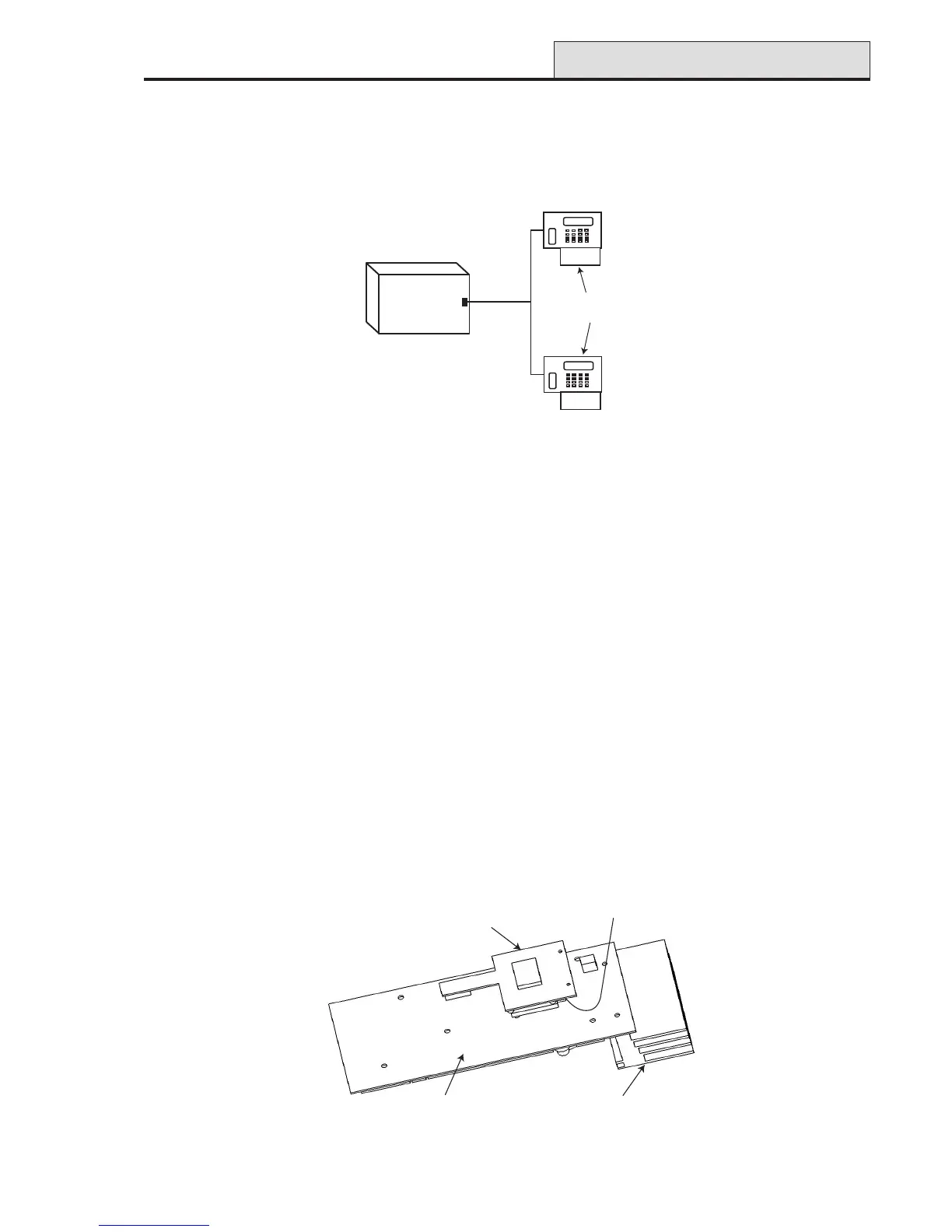
Figure 15. GSM Module fitted to underside of Galaxy 2-44 PCB
Built-in Dialler/Modem
The built-in dialler allows signalling to an Alarm Receiving Centre (ARC), SMS signalling and remote servicing
from a PC.
LED’S
There are two LED’s on the Galaxy 2 Series PCB. Pulsing of the red LED1 indicates an active telecommuni-
cations. Illumination of the green LED2 indicates the presence of AC mains supply.
Audio Header (2–44+ Only)
This is a 14-way shrouded header for audio connection. When an alarm is received at the ARC, the ARC can
communicate through a loudspeaker at the premises, and ask for a password before authenticating the alarm.
GSM Interface (2–44+ Only)
This module provides a mobile telecommunications interface to provide an alternative to the land line. The
GSM interface provides the same functionality as the built-in dialler/modem. The module attaches to the
underside of the PCB and also connects to the antenna on the edge of the enclosure box.
ECP Bus (2–44+ Only)
The ECP bus can operate at the same time as the RS485 bus. The cable can be standard 4-core and can be
spurred or T wired.
The maximum length of cable run is 100 metres.
Figure 14. ECP Line - T Wire Configuration
ECP Bus
GSM
Module
Heatsink
to antenna on
enclosure box
Galaxy
2-44 PCB
(underside)
Galaxy 2-44
Control Panel
Keypad
OR
Peripheral
ECP Bus

 Loading...