24
Galaxy 2 Series Installation Manual
Peripherals - Installation, Wiring & Addressing
Configuring
New peripherals will be configured onto the system at system power up or on learning programming mode.
Changes to peripheral addresses will only take effect when the peripheral is re-powered.
General
The following peripherals can be connected to the Galaxy 2 Series:
RS485 Bus: Mk7 LCD Keypad/Keyprox; RIO; PSU; Wireless Receiver.
NOTE: Up to four keypads (including keyprox) can be fitted to this line. Keypads/keyproxes must be wired
in daisy chain configuration (see RS485 Wiring Configuration). The maximum length of cable for
all peripherals on this line is one Km.
ECP Bus (2–44+ only): 6160 Keypad/Keyprox; 5800 RF receiver; ECP zone expander.
NOTE: Up to four keypads can be fitted to this line. Keypads can be wired to the control panel indepen-
dently, in series or in star configuration. The maximum cable length for all peripherals connected to
this line is 100m.
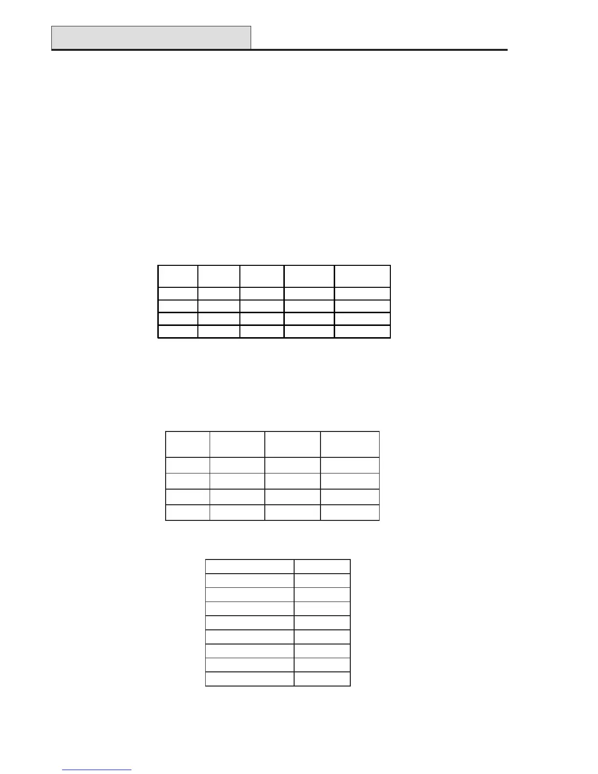
Table 5. RS485 Peripheral Wiring
Table 6. ECP Peripheral Wiring
The following table identifies the peripheral addresses:
Table 7. Peripheral Addresses
LENAP
0616
DAPYEK
0085
REVIECER
ENOZ8+4
REDNAPXE
+XUA
+)der(+P/IV21+
-XUA
-)kcalb(--
OD
Y∇ )wolley(ODOD
ID
G∆ )neerg(IDID
Peripherals
NOTE: No two peripherals connected can share an address, regardless of the data bus to which they are
connected.
LAREHPIREPSSERDDA
xorpyek/dapyeK7kM3-0
OIR5-2
USP5-2
revieceRsseleriW5-4
dapyeK06163-0
xorpyeK06165-4
revieceRFR008
55-4
rednapxEenoZPCE4-2
PANEL
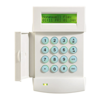
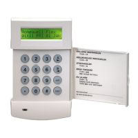
Mk7 LCD
KEYPAD
RIO PSU
Wireless
Receiver
AUX+
++ + +
AUX-
-- - -
A
AA A A
B
BB B B

 Loading...