12
Galaxy 2 Series Installation Manual
Zones
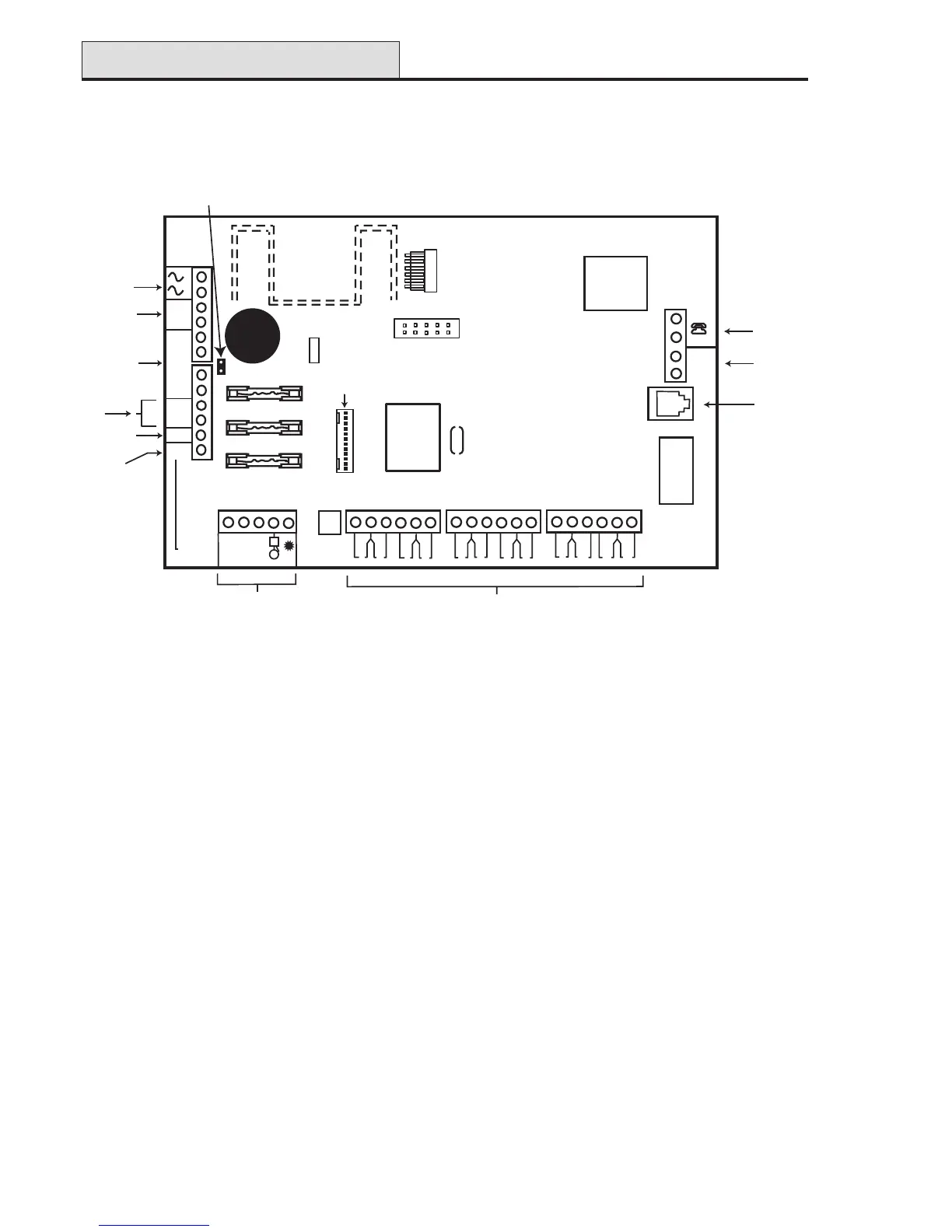
PCB Layout (2–20)
Figure 5. Galaxy 2–20 PCB Layout
X1
B
A
LINE IN
B
A
9
10
11
12
1
2
3
4
5
6
7
8
COM N/O BELL
+12v
0V T
TRIG
(N/C)
LS
B
A
+
+
AUX
-
-
BATT +
BATT -
F1 (1 amp)
BATT
F2 (0.5 amp)
F3 (0.5 amp)
AUX
BELL
PROG HEADER
Power
LED
AC Power
Input
Battery
Terminals
12 Volt
Auxilliary
Output
Loudspeaker
Negative
Trigger
Output
SAB
Connections
Zone Terminals
Extension
Phone
Output
Phone
Line
Input
Alternate
Phone
Socket
Trigger
Header
RS 485
lines
Note: Switch SW1 and the
tamper spring are for the
plastic box only.
The metal box has a 2-way
terminal for connection to
the lid tamper microswitch.
Note: If Relay is fitted the TRIG terminal
is used as N/C for Relay.
If Relay is not fitted the COM & N/O terminals
are not fitted. The TRIG N/C terminal is
the transistorised output.
2-way header
RS485 termination

 Loading...