7
Galaxy 2 Series Installation Manual
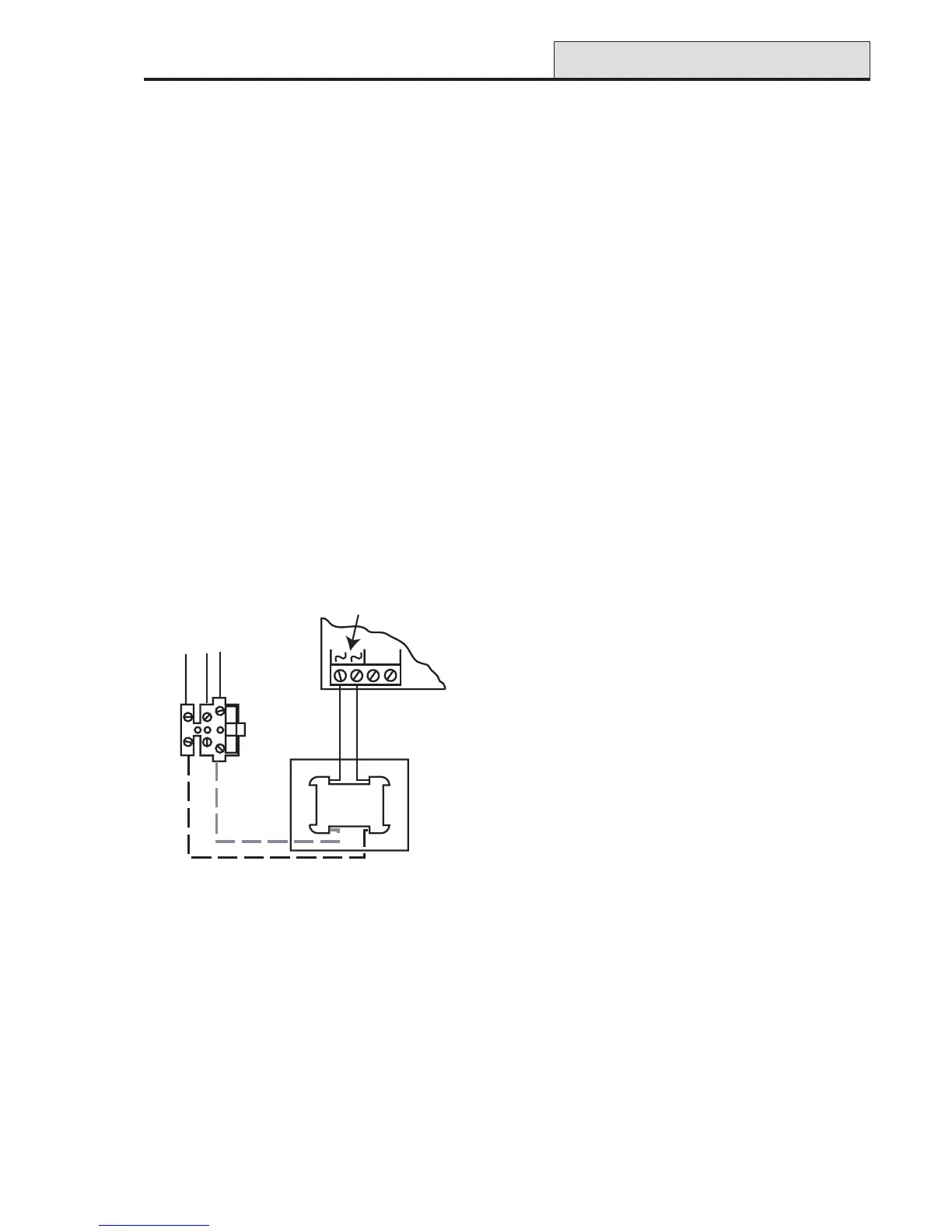
NOTE: Connections shown as dashed lines
are factory made. The metal box
must be earthed.
Figure 2. Mains Connection to the Galaxy 2 Series
The outer covering insulation must be clamped under the cable clamp. It is important that this cable enters the
control panel enclosure through the mains entry hole next to the mains terminal block, is not looped within the
control panel enclosure and does not run close to other system cables inside or external to the enclosure.
WARNING: The control panel enclosure must not be opened before isolating the mains supply.
Illumination of the green power LED 2 indicates the presence of a.c. mains supply. The
cover of the Galaxy 2 Series enclosure must be replaced whenever any connection to the
BT master socket is completed to prevent exposure to potentially lethal voltages from the
PSTN.
System Wiring (cont’d)
Zone and Data Cable Type
Zone cables and all cables between the panel, keypads and expansion modules must be as follows:
RS485 Bus: Twisted pair screen cable Belden 8723 equivalent. For systems with less than 100m cable run
in total, standard 4-core alarm cable may be used in most normal environments.
ECP Bus and Zone Cables: Standard 4-core alarm cable.
Zones: Standard 4-core alarm cable.
Mains Supply Connection
The connection to the a.c. mains supply must be made by a competent, qualified person, for example NICEIC
approved, in accordance with the current IEE and local supply regulations.
Warning: A means of isolation from the mains supply must be provided within two metres of the
control panel. Where live and neutral supplies can be identified, a fused spur with a 3A
fuse, must be fitted on the live circuit. Where live and neutral circuits cannot be reliably
identified, 3A fuses must be fitted to both circuits.
Where a flexible cable is connected to the control having cores coloured brown and blue it is important to
connect the wires to the mains terminal block as follows:
• Blue (Neutral) – connect to terminal N
• Green/Yellow (Earth) – connect to terminal E
• Brown (Live) – connect to terminal L
From a.c. mains input
(entering next to terminal block)
Brown Wire
Blue Wire
Galaxy 2 Series PCB
Mains Transformer
Primary Side
Mains Transformer
Secondary Side
200 mA
mains fuse
TB2
Batt+ Batt-
AC Power

 Loading...