34
Galaxy 2 Series Installation Manual
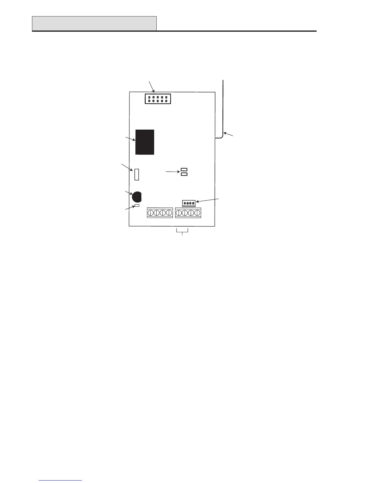
V2 Wireless Receiver
Up to two receivers can be connected to the RS485 (AB) line. The V2 Wireless Receiver acts as an RF
receiver for the Honeywell 868MHz transmitter range.
Figure 25. V2 Wireless Receiver
V2 Receiver Tamper
Switch SW2 on the Receiver acts as a tamper if the tamper link LK1 is missing.
Addressing the V2 Receiver
The Receiver must be given a unique address before it is connected to the power supply. This address is
selected via the Address Setup Jumper and can be 4 or 5.
To set the address as 4, fit the jumper to one pin only (open) of Address Setup Jumper LK2.
To set the address as 5, fit the jumper across the two pins (shorted) of Address Setup Jumper LK2.
LED’s
The PWR LED gives power and communication status (see Table 9 - RIO LED Flash Rates for informa-
tion on the meaning of the various flash rates).
The RF LED will blink upon reception of decodeable signals. If a jam condition occurs (continuous interfer-
ence), the LED will come on constantly. It will switch off again only when the jam condition clears.
Wireless Receiver
PANEL
B
A
-
+
SW2
LK1
Tamper
link
Tamper
switch
Address
Setup
Jumper
Processor
Program
Header
Antenna
RF
PWR
LED's
RS485
line
Engineer
Header
B
A
-
+
PERIPHERAL
SW1
ADDR
LK2

 Loading...