29
Galaxy 2 Series Installation Manual
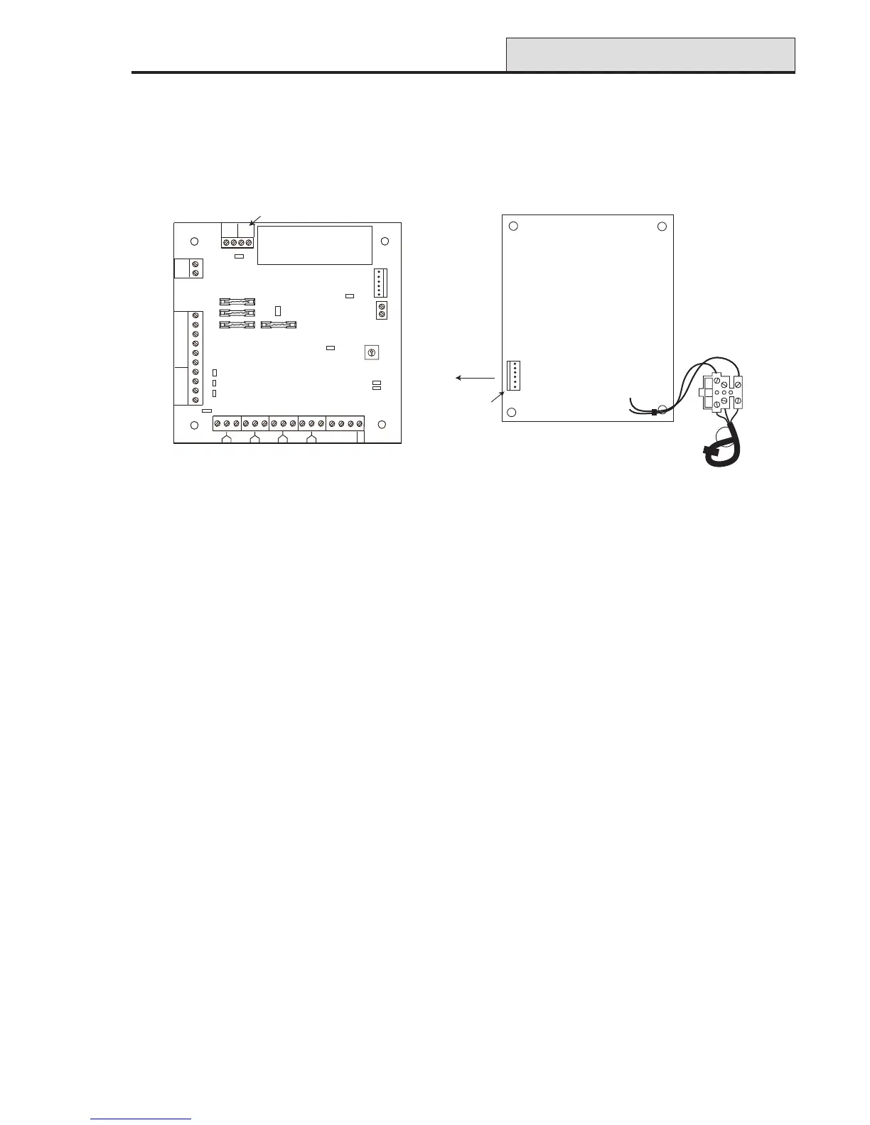
Figure 20. Power Supply Unit
PSU
Power Supply Unit
The Galaxy 2 Series Power Supply Unit (PSU) is available in two variants.
The Galaxy Power Unit is a 3-ampere power supply. The Galaxy Power RIO is a Power Unit plus an on-
board Remote Input Output (RIO) module. Both variants are configured in the same way.
Configuration
The Galaxy Power Supply Unit (PSU) consists of two modules, the Power Block and the Control Unit. The
PSU can be connected to the Galaxy 2 Series control panel via the RS485 (AB) line. The PSU can be used in
place of a standard RIO to overcome power problems that arise when the additional RIO is fitted distant to
the control panel.
A 6-way jumper lead connects the Power Block to the Control Unit.
The PSU (Power RIO variant) has eight zones and four outputs. Each variant of the PSU takes one of the
four RIO address (2 - 5). Addressing is identical to that described for RIO Modules.
The four outputs are switched 0V (0V active). Without the jumper links (LK1-4) fitted, the outputs will float in
the OFF state. They can apply a +12V signal, if required, by fitting the appropriate pull-up jumper supplied.
LK5 will short out the off-wall tamper if it is not used.
The SLAVE and E/E links must be in place for normal operation.
FAULT OP AC: This is an open collector transistor which is normally off. The output is activated by an AC
failure.
FAULT OP BAT:This is an open collector transistor which is normally off. The output is activated by a
Battery Low or Battery Fail condition.
FAULT OP POWER: This is an open collector transistor which is normally off. The output is activated by
low voltage present in +12V1 or +12V2 .
Mains
Terminal
Block
Power
Header
To Control
Unit
Power Block
NEUTRAL
LIVE
13.8V
0V
14.5V
0V
BT
AC/F
WARNING: The Power Block PCB
is connected to mains voltage. Always
disconnect mains supply for at least
1 minute before removing the box lid.
1 1/2 2
3
3/4
4
5
5/6
6
7
7/8
8
Zones 1-8
HEATSINK
Comms
Line
Outputs
Rotary
Address
Switch
AC
BAT
PWR
0V
OP1
OP2
OP3
OP4
LID
TAMP
OW
TAMP
+14.5
0V
+12V1
A(DO)
B(DI)
F1
F4
F3
F2
LK1
LK2
LK3
LK4
-BAT
+BAT
AC/F
BT
0V
14.5
0V
13.8
LED1
(comms)
LED2
(AC)
Control Unit
+12V2
0V
0V
FAULT OP
Off-wall
Tamper
From
Power
Block
Bell-Box
connection
LK5
LK10
SLAVE
E/E

 Loading...