When the enabled interrupt signal
is
received
it
activates
the
chip
interrupt
(INTRPT)
output
signal which
is
sent
to
the system. When
all interrupts are disabled, the Interrupt Enable Register and the
INTRPT
output
signal are disabled. The other registers are
not
affected.
Bit 7
of
the
Line
Control Register
(XFB)
determines
whether
the
divisor latch
MSB
or the Interrupt Enable Register
is
accessed.
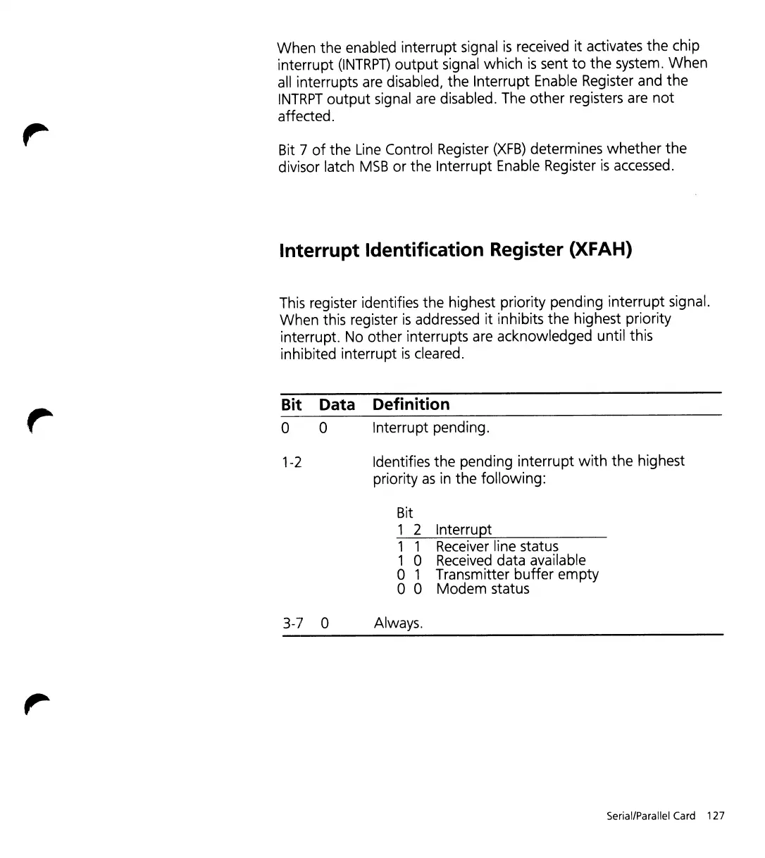
Interrupt Identification Register (XFAH)
This register identifies the highest priority pending interrupt signal.
When this register
is
addressed it inhibits
the
highest priority
interrupt. No other interrupts are acknowledged until this
inhibited interrupt
is
cleared.
Bit
Data Definition
a 0 Interrupt pending.
1-2
Identifies the pending interrupt
with
the
highest
priority
as
in the following:
Bit
1 2 Interrupt
1 1 Receiver line status
1 0 Received data available
o 1 Transmitter
buffer
empty
o 0 Modem status
3-7 0 Always.
Serial/Parallel
Card
127