B_configure.doc 125 Tue Jul 2 15:27:17 1996
125
Changing Your Workstation’s Hardware Configuration
Installing Additional memory
Perform the following steps to add memory modules to your workstation.
1 Remove the main tray assembly according to the directions in “Removing the
Main Tray Assembly” earlier in this appendix.
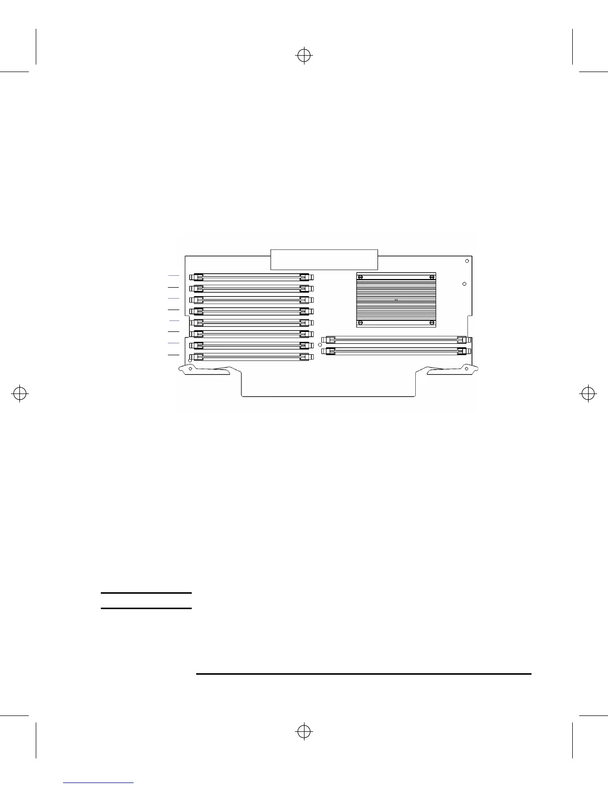
2 Use Figure 36 to locate the memory modules on the CPU Assembly.
Figure 40 Memory Connectors (Model C160L)
This workstation has 8 memory slots, labeled 0A, 0B through 3A, 3B. The mem-
ory configuration is 32 MB to 512 MB installed in pairs of 16 MB, 32 MB, or 64
MB memory modules.
Memory modules must be installed in pairs of equal capacity.
Always install the largest capacity memory modules in the lowest numbered
memory slots.
For example, if you have a pair of 16 MB memory modules and a pair of 64 MB
memory modules, first install the pair of 64 MB memory modules in slots 0A
and 0B, then install the 16 MB modules in slots 1A and 1B.
NOTICE: Memory slots must be filled in order from 0A and 0B through 3A and 3B.
3 Close the ejector tabs on each side of the memory connector to lessen the force
needed to seat the memory module. See Figure 41.
0A
2A
0B
2B
1A
3A
1B
3B