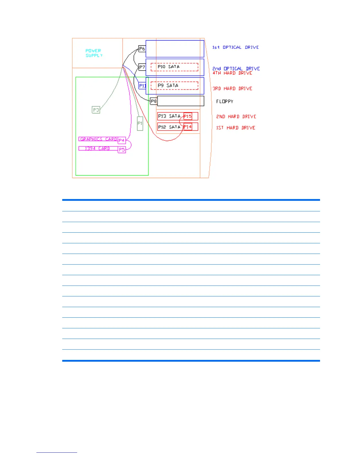
Figure 4-31 Identifying the correct power connections for a typical configuration
P1 Main power on system board
P2 N/A
P3 CPU power
P4 PCI Express graphic auxiliary
P5 PCI auxiliary (e.g. 1394)
P6 ODD IDE top bay
P7 ODD IDE mid bay
P8 FDD
P9 3rd HDD SATA bottom ODD bay
P10 4th HDD SATA mid ODD bay
P11 ODD IDE or 3rd HDD SAS ODD bottom bay
P12 1st HDD SATA bottom HDD bay
P13 2nd HDD SATA top HDD bay
P14 1st HDD SAS bottom HDD bay
P15 2nd HDD SAS top HDD bay
ENWW Steps for removal and replacement of components 85
 Loading...