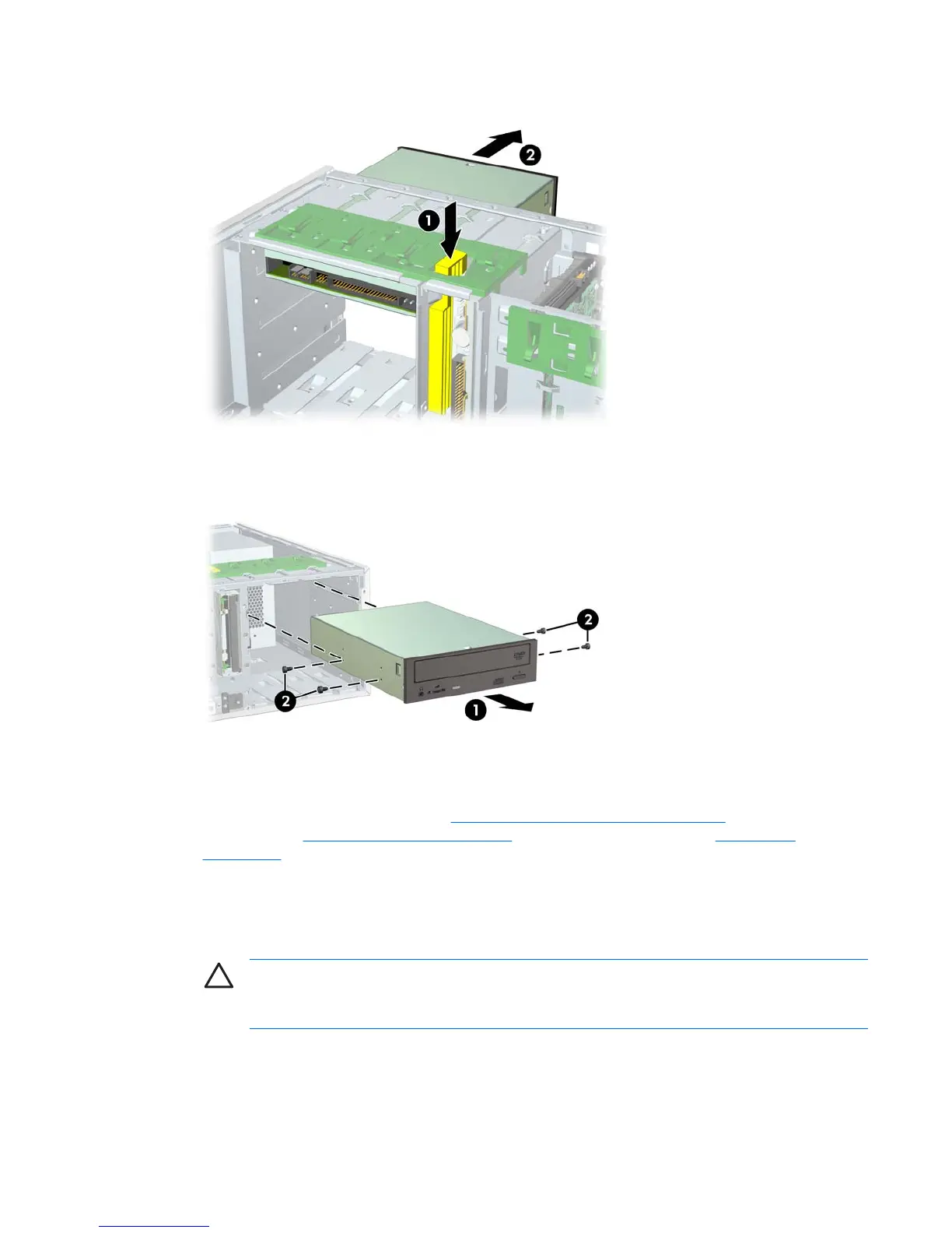
3. Press down on the yellow drive-lock release lever 1 and gently slide the drive 2 out of the chassis.
Figure 4-37 Removing the optical drive from the chassis
4. After pulling the drive 1 out, remove the four guide screws 2 from the drive. Only remove the four
guide screws if you plan to install another drive.
Figure 4-38 Removing the optical drive screws
To install an optical drive:
1. Disconnect power from the system (
Predisassembly procedures on page 60), remove the side
access panel (
Side access panel on page 66) and remove the front bezel (Front Bezel
on page 67).
2. Insert the four guide screws 1 into the drive.
3. Align the screws with the grooves in the drive bay and gently slide 2 the drive into the unit until it
snaps into place.
CAUTION Ensure that the optical drive is secure by pulling to see if the drive can become
easily disengaged. Failure to do so can cause damage to the drive when moving the
workstation.
ENWW Steps for removal and replacement of components 89
 Loading...