2. Wiring
Fieldbus Communication
51
RCP6
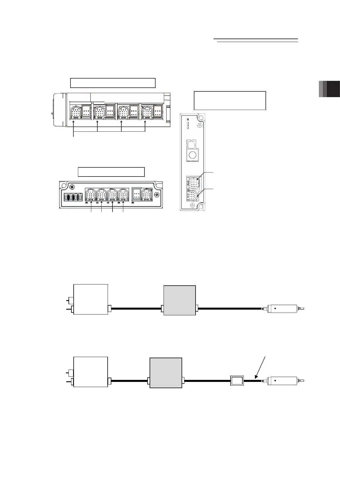
■ Connection among Hub Unit, RCP6S Gateway Controller and Actuators
Shown below is a cable layout diagram and model numbers when a controller for RCP6S
Gateway is to be connected to a hub unit.
It is available that a controller for RCP6 Gateway is connected directly to the gateway unit
without using a hub unit. In this case, the controller should be connected to the axis control
connector.
[D] When connection is established with a pulse motor type actuator (RCP5 or 6)
Connect a controller for RCP6S Gateway to the hub unit (or a gateway unit) and connect a
RCP5 or 6 actuator on the further end.
[E] When connection is established with a pulse motor type actuator (RCP2 to 4)
Connect a controller for RCP6S Gateway (RCM-P6PC) to the hub unit (or a gateway unit) and
connect a RCP2 to 4 actuator on the further end via a connector conversion unit.
RCP2 to 4
ctuato
Connector
Conversion Unit
RCM-CV-APCS
5) RCP6S
Gateway
Connector
3) RCP6S
Connector
RCP6S
Gateway Controller
Power axis
Supply Control
Connector Connector
Each Actuator
Connector
RCP5 and 6
ctuato
5) RCP6S
Gateway
Connector
3) RCP6S
Connector
RCP6S
Gateway Controller
Power axis
Supply Control
Connector Connector
Hub Unit
RCP6S
Connector
Hub Unit
RCP6S
Connector
Gateway Unit (Bottom Surface)
Hub Unit (Front
Surface
)
No. 0 No. 4 No. 8 No. 12
Axes Control Connector
Axes Control Connector
Connected unit: RCP6S Gateway Controllers
(Hub unit not used)
Connected unit:
Each Actuator or Connector Conversion Unit
Power Supply Connector
Connected unit: Hub Unit or Gateway Unit
RCP6S Gateway Controllers
(Front
Surface
)
RCP6S Connector
Connected unit: RCP6S Gateway Controllers

 Loading...