Chapter 3 Operation
93
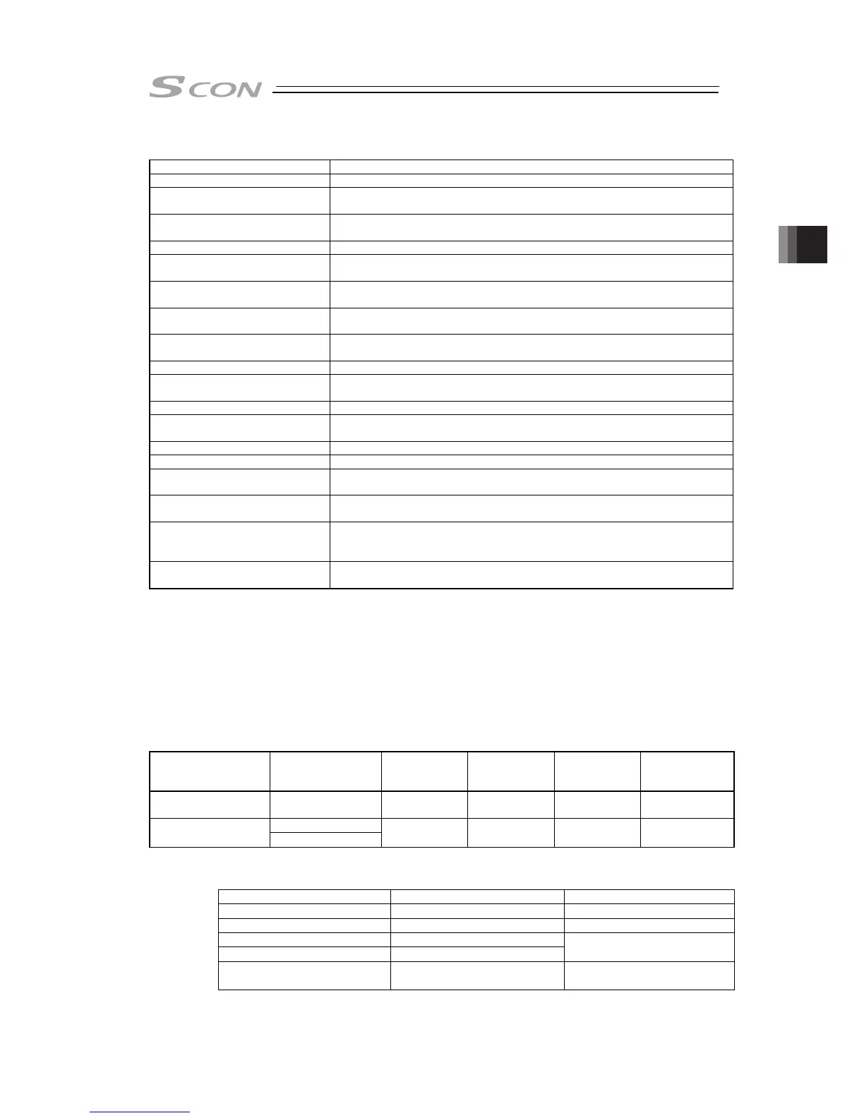
[2] Overview of major Functions
Function Description
Number of positioning points Number of positioning points which can be set in the position table.
Operation with the Position No.
Input
Normal operation started by turning the start signal ON after position No. is
entered with binary data.
Position No. direct command
operation
Operation enabled by turning the signal directly corresponding to a position
No. ON
Positioning Positioning enabled at an arbitrary position by the data set in the position table
Velocity change during the
movement
Velocity change enabled by activating another position No. during movement
Pressing (tension) Operation by an arbitrary pressing (tensile) force set in the position table
enabled
Pressing in use of force sensor
(dedicated for SCON-CA)
Highly precise pressing enabled by measuring the current pressing force by
using a force sensor (loadcell) to control it
Pitch Feeding
(relative moving feed)
Pitch feed by an arbitrary moving distance set in the position table enabled
Home return signal input Input signal exclusively used for home return. Set to ON to start home return
Pause The operation can be interrupted or continued by setting this signal to ON or
OFF, respectively.
Jog moving signal The actuator can only be moved while the input is set to ON.
Teaching signal input (Current
Position Writing)
Setting the input signal to ON allows the coordinate value in the stop state to
be written to the position table.
Brake release signal input The brake (option) can only be released while the input is set to ON.
Moving Signal Output The output signal is set to ON while the actuator is moved.
Zone signal output The output signal is set to ON while the actuator is entered within the zone
defined by the coordinate values set as parameters.
Position zone signal output The output signal is set to ON while the actuator is entered within the zone
defined by the coordinate values set in the position table.
Position detection feedback
pulse output
(dedicated for SCON-CA)
Feedback pulses sent out from the encoder can be subject to differential
output.
[Refer to Section 3.3 Operation in Pulse Train Control Mode for details.]
Vibration Control Vibrations of the load installed on the actuator can be suppressed. However,
this is invalid in the home return and pressing operations.
[3] Operation modes of rotary actuator in multiple rotation mode and command
limitations
An actuator of multi-rotation specification includes two operation modes, or the normal mode
enabling only a limited number of rotations and the index mode
Note 1
enabling a number of
rotations. A specific operation mode can be selected by parameter No.79 “Rotational axis
mode selection”. Parameter No.80 “Rotational axis shortcut selection” allows the shortcut to
be made valid or invalid.
The table below lists the settings of parameters and the operation specification in each mode.
Rotary axis mode
Parameter No.79
Rotational axis
shortcut selection
Parameter No.80
Current
position
indication
Absolute
position
command zone
Relative
position
command zone
Soft Limit
Enabling/
Disabling
0 (Normal Mode) 0 (Disabled)
-9999.99
to 9999.99
Note 2
-0.15
to 9999.15
Note 2
-9999.30
to 9999.30
Note 2
Enabled
0 (Disabled)
1 (Index Mode)
1 (Enabled)
0 to 359.99 0 to 359.99
-360.00
to 360.00
Disabled
Note 1: Index Mode cannot be used in the actuators except for absolute type with the DD motor.
Note 2: It is limited within the range of the software limit.
The following models can not be rotated up to 9999.99 [deg].
deceleration ratio Maximum rotation angle [deg] corresponding model
1/24 ±7679.99 RCS2-RTC8, RCS2-RTC10
1/30 ±6143.99 RCS2-RTC12
1/50 ±3685
1/100 ±1842
RS-30, RS-60
Multi-rotation absolute
(High resolution specification)
±2520 DD Motor