Chapter 3 Operation
181
[3] Electric Gear Settings for Feedback Pulse
This is the parameter to determine the output pulse corresponding to the actuator movement
amount. Determine the movement amount per pulse to define how many millimeters you would
like the actuator to move with the output of 1 pulse.
Movement in line axis per pulse = Minimum output unit (1, 0.1, 0.01mm etc.)/pulse
Movement in rotary axis per pulse = Minimum output unit (1, 0.1, 0.01deg etc.)/pulse
(1) Selecting used feedback pulse gear ratio (Parameter No.114)
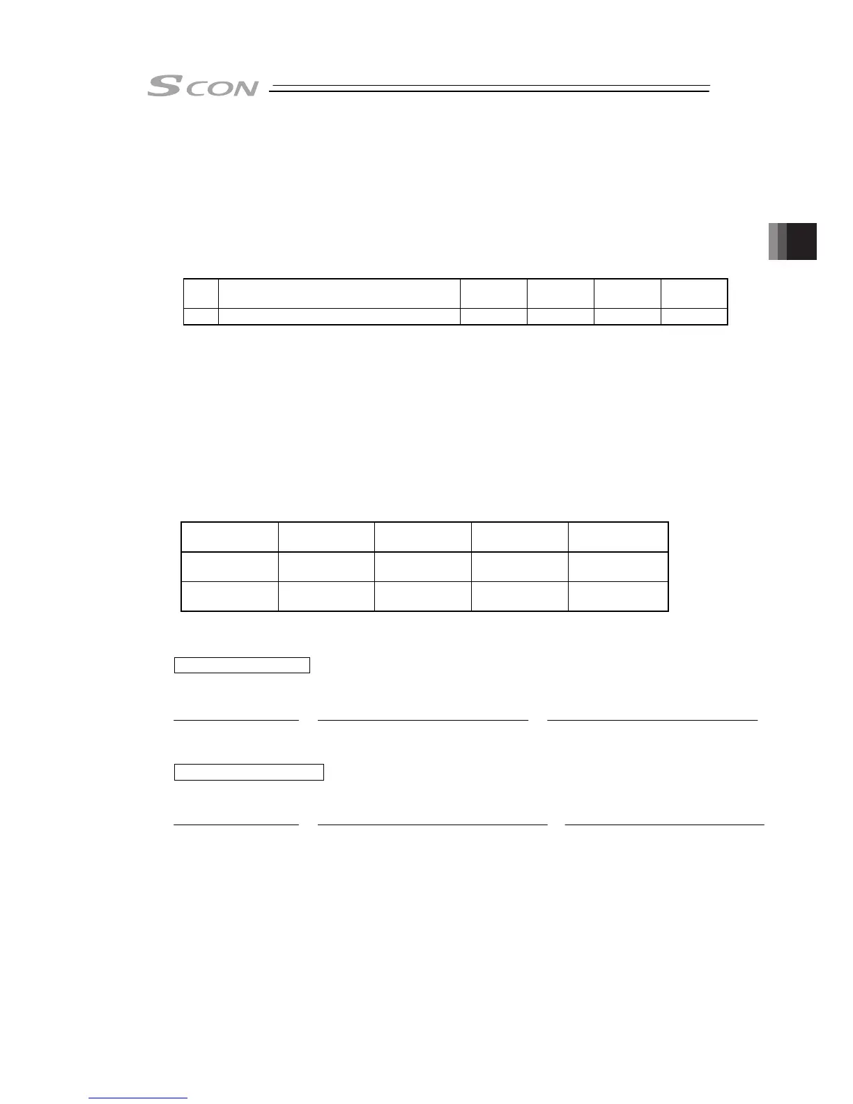
No. Name Symbol Unit
Input
Range
Initial
Value
114 Selecting used feedback pulse gear ratio
FPIO – 0 to 1 0
0: It outputs the pulse equivalent to the input pulse.
If the movement amount of input pulse is 0.01mm, 1 pulse is output when moved for
0.01mm. Thus, 1 pulse is output in response to 1 pulse of input.
Output pulse is determined by the electric gear for input (Parameters No.65 and 66).
1: The relation of the output pulse and the actuator movement can be set freely. Set the
electric gear in Parameters No.115 and 116.
(2) Electrical Gear (Feedback Pulse) (Parameter No.115, No.116)
Set these parameters when the relation of the output pulse and the actuator movement are to
be set freely.
These parameters are enabled when Parameter No.114 is set to 1.
User Parameter No.115/116 Electronic Gear (Feedback Pulse) Numerator/Denominator
Name Symbol Unit Input Range
Initial Value
(For reference)
Electronic Gear
Numerator
FNUM – 1 to 4096 125
Electronic Gear
Denominator
FDEN – 1 to 4096 2048
Electronic Gear Formula:
In the case of Line Axis
In the case of Rotary Axis
Note 1 : Refer to 10.4 List of Specifications of Connectable Actuator for the encoder pulse of
each actuator.
Formula for velocity:
The velocity of the actuator is in proportion to the frequency of the output pulse.
Velocity = Movement amount per pulse × Output Pulse Frequency [Hz]
Electronic Gear
Numerator (FNUM)
Electronic Gear
Denominator (FDEN)
=
Ball Screw Lead Length [mm/rev]
No. of Encoder Pulses [pulse/rev]