Chapter 2 Wiring
43
Chapter 2 Wiring
2.1 Positioner Mode (PIO Control)
2.1.1 Wiring Diagram (Connection of Construction Devices)
2.1.1.1 SCON-CA
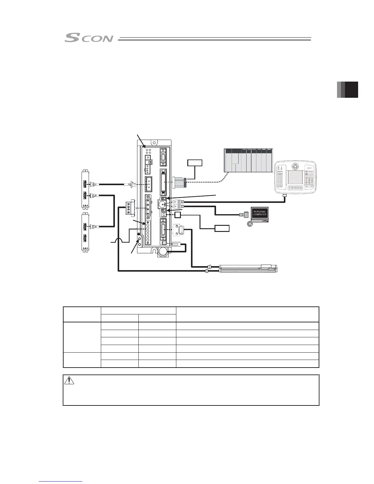
[1] Basic Wiring Diagram
Power Supply for Brake
It is necessary when actuator with brake
Note 1 Please prepare separately.
Absolute Battery
(for Absolute Type)
PC Software (option)
(Note1)
Actuator
Teaching pendant (option)
PLC
(Note1)
Regenerative Resistor Unit
(RESU-1 [for secondary unit] : option)
Regenerative Resistor Unit
(RESU-2 : option)
Required depending
on usage condition
[Refer to 1.5.3 Regenerative Unit]
Power
Supply
Connector
Flat Cable
(Accessories)
CB-SC-REU010
CB-ST-REU010
FG Connection
Terminal
24V DC
24V DC
Power Source
Single Phase
100V AC or
200V AC
Power Source for
I/O Control
(Note1)
LED Display
Changeover Switch
Brake Release
Switch
If using RCS-RA13R or NS Type for the actuator and the option shown in the table is applied, the
wiring between the actuator and the controller will differ from the basic wiring layout. Shown in the
table is the relation of the option and wiring layout.
Option
Model Name
Brake Loadcell
Wiring Layout between Actuator and Controller
○ × (1)
× ○ (2)
○ ○ (3)
RS-RA13R
× × Basic Wiring Diagram
○ - (1)
NS
× - Basic Wiring Diagram
Caution : Turn OFF the power to the controller before inserting or removing the connector for
connection between the teaching tool and controller.
Inserting or removing the connector while the power is turned ON causes a controller
failure.