Chapter 2 Wiring
82
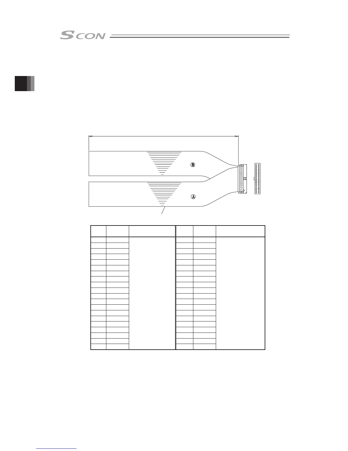
2.3.4 Connection of PIO
Conduct the connection of I/O to the controller is to be carried out using the dedicated I/O cable.
Cable length is to be indicated in the controller model code. Please check the controller model
code. A desired I/O cable can be selected from 2m (standard), 3m, and 5m cables. Up to 10m
I/O cables are sold separately.
Also regarding the cable for connection to the host controller (PLC, etc.), the terminal end is just
cut and no connector is attached nor any treatment is applied so the user can make a free
wiring layout.
Model : CB-PAC-PIO□□□
(□□□ indicates the cable length L. Example. 020 = 2m)
Half Pitch MIL Socket
HIF6-40D-1.27R (Hirose Electric)
Flat Cable (20-core)
×
2
L
20A 20B
1A 1B
No connector
No connector
No.
Cable
Color
Wiring No.
Cable
Color
Wiring
1A BR-1 1B BR-3
2A RD-1 2B RD-3
3A OR-1 3B OR-3
4A YW-1 4B YW-3
5A GN-1 5B GN-3
6A BL-1 6B BL-3
7A PL-1 7B PL-3
8A GY-1 8B GY-3
9A WT-1 9B WT-3
10A BK-1 10B BK-3
11A BR-2 11B BR-4
12A RD-2 12B RD-4
13A OR-2 13B OR-4
14A YW-2 14B YW-4
15A GN-2 15B GN-4
16A BL-2 16B BL-4
17A PL-2 17B PL-4
18A GY-2 18B GY-4
19A WT-2 19B WT-4
20A BK-2
Flat Cable
○
A
(Press Welding)
AWG28
20B BK-4
Flat Cable
○
B
(Press Welding)
AWG28
For the signal assignment of each wire, refer to the following considering the operation
mode.
1) Positioner Mode ························2.1.3 [5] PIO Circuit
2) Pulse Train Control Mode ············2.2.3 [5] PIO Circuit