Chapter 3 Operation
109
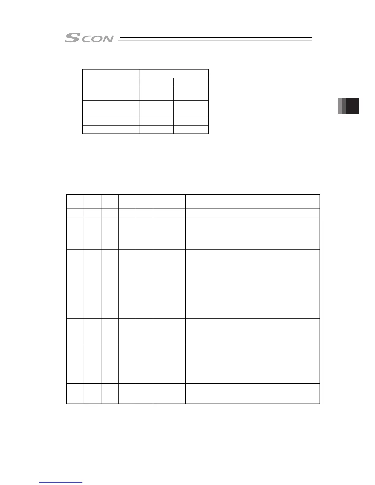
[7] Binary Output of Alarm Data Output (*ALM, PM1 to 8)
Output
PIO signal
*ALM PM1 to 8
Common to Patterns
0 to 3
{ {
Pattern 4
(Note 1)
{
×
Pattern 5
(Note 1)
{
×
Pattern 6
{ {
Pattern 7
(Note 1)
{
×
{ : Available, ×: Unavailable
Note 1 Patterns 4, 5, and 7 do not have this function.
1) If an alarm at a level equal to or higher than the operation release level occurs, completed
position number output signals PM1 to PM8 output the alarm information in the binary code
format.
2) The PLC can read the binary code of alarm signal *ALM as the strobe signal to refer to
alarm information.
{: ON z: OFF
*ALM
ALM8
(PM8)
ALM4
(PM4)
ALM2
(PM2)
ALM1
(PM1)
Binary Code
Description: Alarm code is shown in ( ).
{ z z z z
–
Normal
z z z { z
2
Software reset during servo ON (090)
Position number error during teaching (091)
PWRT signal detected during movement (092)
PWRT signal detected before completion of home return
(093)
z z z z {
3
Move command during servo OFF (080)
Position Command in Incomplete Home Return (082)
Absolute position move command when home return is
not yet completed (083)
Movement Command during Home Return Operation
(084)
Position No. error during movement (085)
Move command while pulse train input is effective (086)
Move command during loadcell calibration (087)
Position Command Data Error (0A3)
Command Deceleration Error (0A7)
z z { z z
4
FAN error detection (0D6)
Drive mode error (0DD)
Field bus module not detected (0F3)
Mismatched PCB (0F4)
z z { z {
5
Loadcell data error (0A9)
Loadcell calibration error (0E1)
Loadcell communication error (0E2)
Loadcell error (0E3)
Field bus link error (0F1)
Field bus module error (0F2)
z z { { z
6
Parameter data error (0A1)
Position data error (0A2)
Unsupported motor/encoder type (0A8)
(Note) *ALM Signal is an active low signal. It is ON when the power is applied to the controller, and
turns OFF when the signal is output.