Chapter 2 Wiring
70
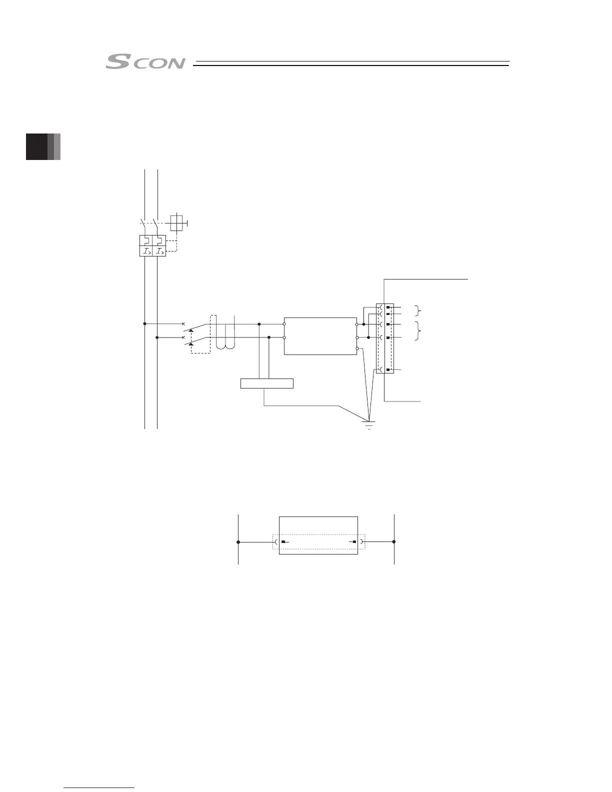
2.2.3 Circuit Diagram
Sample circuit diagrams are shown below.
[1] Main Power Circuit
Surge Protector
Noise Filter
[Refer to 2.3.1]
Earth Leakage Breaker
Circuit Breaker
PE
Motor Power Unit
Control Power Supply
L1 L2
L1
L2
L1C
L2C
SCON
Power Supply Input Connector
(Note) The power voltage of the controller (100V AC or 200V AC) cannot be changed.
[2] Brake Power Supply Circuit
Brake Power Supply Connector
BK PWR
+-
24V DC 0V
SCON
(Note) Supply 24V DC if the used actuator is equipped with a brake.