Chapter 2 Wiring
69
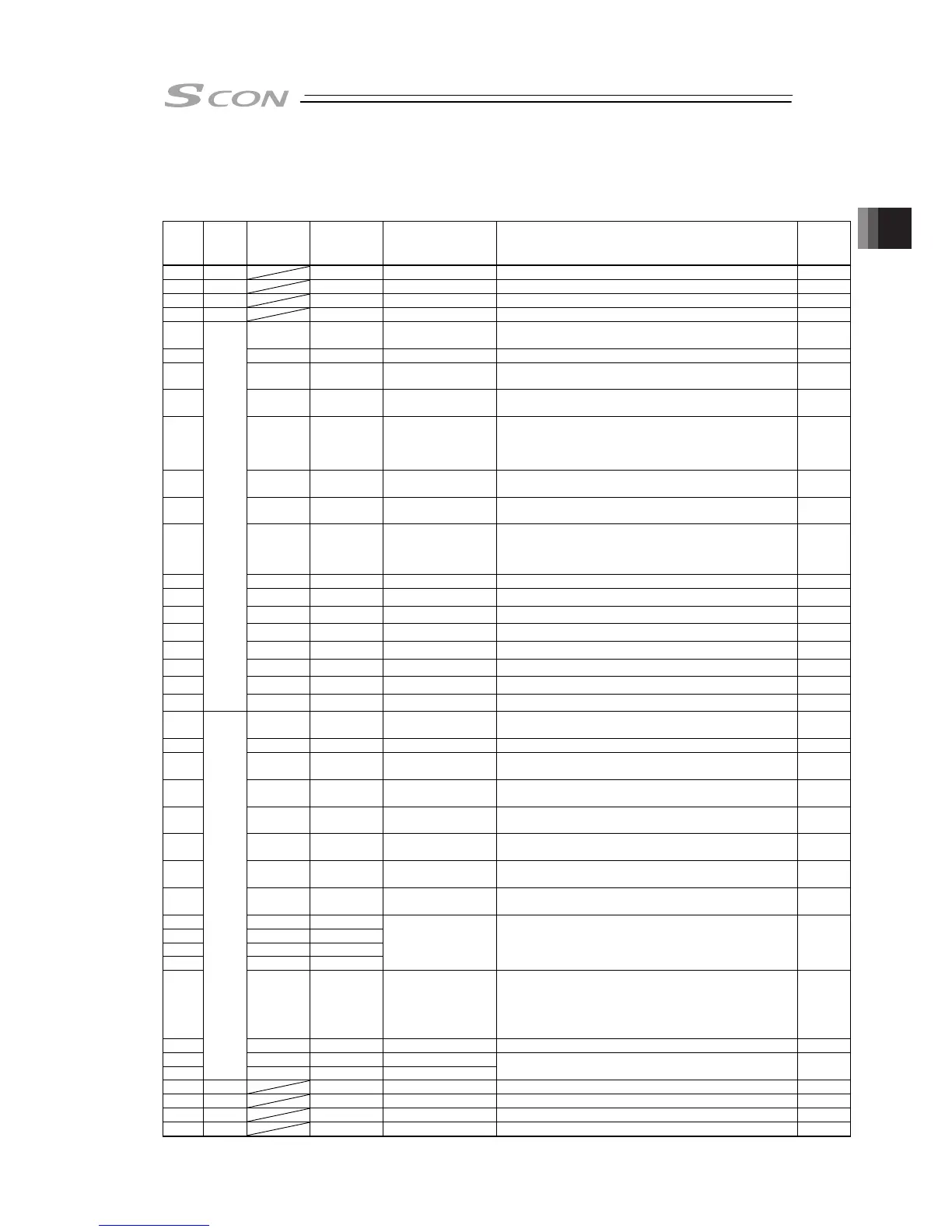
2.2.2 I/O Signals in Pulse Train Control Mode
The table below shows the signal assignment of the flat cable in the pulse train control mode.
Follow the following table to connect the external equipment (such as PLC).
Pin
No.
Category
I/O No.
Signal
Abbreviation
Signal Name Function Description
Relevant
Sections
1A 24V P24 Power Supply Power Supply for I/O +24V
2A 24V P24 Power Supply Power Supply for I/O +24V
3A – NC – Not used
4A – NC – Not used
5A IN0 SON Servo ON
The servo remains ON while this signal is ON, or OFF
while this signal is OFF.
3.3.2
6A IN1 RES Reset Turn the signal ON to reset the alarm. 3.3.2
7A IN2 HOME Home Return
The controller will perform home return operation when
this signal is turned ON.
3.3.2
8A IN3 TL Torque Limit Select
Puts torque limitation to the motor with the signal ON and
the value set to the parameter.
3.3.3
9A IN4 CSTP Compulsory Stop
Turning it ON continuously for more than 10ms
compulsorily stops the actuator.
The actuator decelerates then stops with the torque set in
the controller and then turns the servo OFF.
3.3.2
10A IN5 DCLR
Deviation Counter
Clear
Clears the deviation counter.
3.3.3
11A IN6 BKRL
Brake Forcible
Release
The brake will forcibly be released.
3.3.2
12A IN7 RMOD
Operation Mode
Changeover
The operating mode is selectable when the MODE switch
of the controller is set to AUTO.
(The setting is AUTO when signal is OFF, and MANU
when ON.)
3.3.2
13A IN8 NC – Not used
14A IN9 NC – Not used
15A IN10 NC – Not used
16A IN11 NC – Not used
17A IN12 NC – Not used
18A IN13 NC – Not used
19A IN14 NC – Not used
20A
Input
IN15 NC – Not used
1B OUT0 PWR System Ready
This signal turns ON if SCON is controllable after main
power ON.
3.3.2
2B OUT1 SV Servo ON Status This signal will remain ON while the servo is ON. 3.3.2
3B OUT2 INP Position Complete
Turned ON when the remaining moving pulses in the
deviation counter enters within the positioning band.
3.3.3
4B OUT3 HEND
Home return
completion
This signal will turn ON when home return has been
completed.
3.3.2
5B OUT4 TLR
Torque Under
Control
Turns ON if the torque reaches the limit value during
torque limit.
3.3.3
6B OUT5 *ALM
Controller Alarm
Status
Turns ON when controller in normal condition, and OFF
when alarm is generated.
3.3.2
7B OUT6 *EMGS
Emergency Stop
Status
Turns ON when the controller emergency stop is
cancelled, and OFF during the emergency stop.
3.3.2
8B OUT7 RMDS
Operation Mode
Status
The operating mode status will be output. It turns ON
when the controller is on Manual Mode.
3.3.2
9B OUT8 ALM1
10B OUT9 ALM2
11B OUT10 ALM4
12B OUT11 ALM8
Alarm Code Output
Signal
The alarm code is output together with the alarm signal
output.
Refer to Alarm List for details.
3.3.2
13B OUT12
*OVLW/
*ALML
Overload Alarm/
Light Error Alarm
Turns OFF if exceeded the overload warning threshold
(set in Parameter No.143) when Parameter No.151 is set
to 0 (Overload Warning).
It turns OFF when the message level alarm is generated
if Parameter No.151 is set to 1 (Light Error Alarm).
3.3.2
14B OUT13 NC – Not used
15B OUT14 ZONE1 Zone Signal 1
16B
Output
OUT15 ZONE2 Zone Signal 2
This signal will turn ON when the current actuator position
enters the range set by the parameters.
3.3.2
17B – NC – Not used
18B – NC – Not used
19B 0V N Power Supply Power Supply for I/O 0V
20B 0V N Power Supply Power Supply for I/O 0V
Signal with “*” expresses the signal of active low. It is ON when the power is applied to the controller, and
turns OFF when the signal is output.