Chapter 2 Wiring
76
2.3 Wiring Method
2.3.1 Wiring of Power Circuit
Supply the appropriate power from the following considering the controller type.
Power Supply Type Specifications Reference
Motor Power Supply
Control Power Supply
100V Specification : 100 to 115V AC ±10% 50/60Hz
200V Specification : 200 to 230V AC ±10% 50/60Hz
I/O Power Supply
24V DC ±10%
When the PIO is used
Brake Power Supply
24V DC ±10% 1A
For brake equipped type
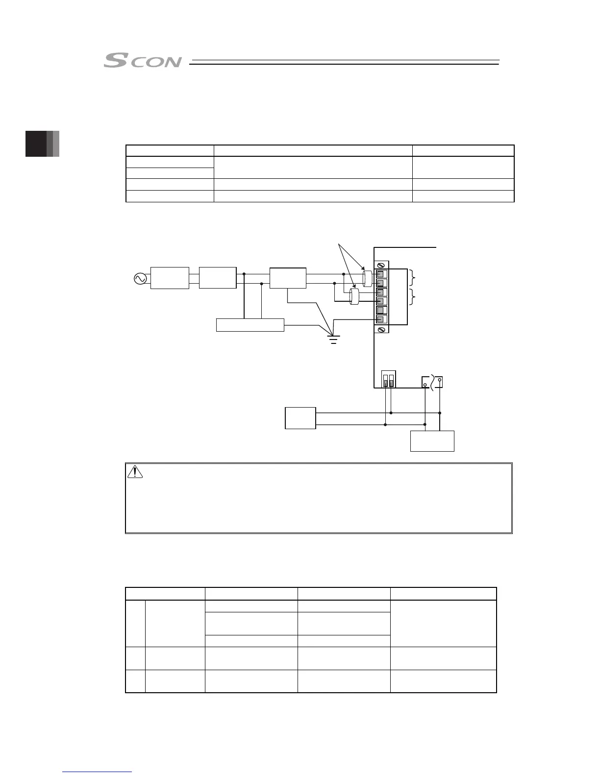
The figure below shows a sample wiring of the power circuit.
L1
L2
L1C
L2C
NC
PE
Circuit
Breaker
Ground Fault
Circuit
Interrupter
1) Noise
Filter
2) Clamp Filter
3) Surge Protector
SCON
100V AC
or
200V AC
PWR
-
BK+
+24V
0V
Brake Power Supply
Input Connector
AC Power Supply
Input Connector
PIO Connector
A. Control Power Supply
B. Motor Power Unit
24V DC
Power
Supply
Brake
Release Box
Caution : Attaching noise filter 1) is a mandatory thing to do. Not doing so may cause
error or unexpected operation to the controller because of noise.
Also, the peripheral devices may receive an influence of this controller noise.
Attach 2) and 3) if necessary considering the noise environment and the power
supply condition. It is recommended to attach them even though it is not
mandatory.
Load current of SCON controller varies depending on the connected actuator, etc. Select the
circuit breaker that suits to the specification.
[Refer to 1.3]
Parts Name Model Supplier Position to attach
NAC-10-472 COSEL
NF2010A-UP
SOSHIN ELECTRIC
CO.,LTD
1) Noise Filter
MC1210 TDK LAMBDA
Attach in range of
300mm or less from
controller
2) Clamp Filter ZCAT3035-1330 TDK
Attach as close as
possible to controller
3)
Surge
Protector
R • A • V-781BWZ-2A
Okaya ELECTRIC
CO.,LTD
Attach at the input
terminal of noise filter