Chapter 2 Wiring
53
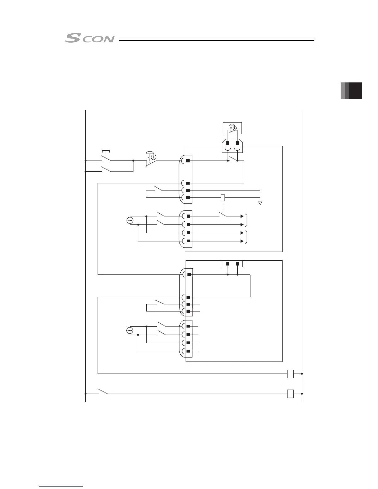
[3] Emergency Stop Circuit
It is the example of circuit layout when an emergency switch of the touch panel teaching or the
teaching pendant is used to the emergency stop circuit of the equipment.
SCON-CA/CAL
24V
Emergency stop
reset switch
Emergency stop
switch
Emergency stop switch
for the teaching pendant
CR1
(Note 1)
0V
MC1
CR1
CR1
S1
S2
S1
S2
1
58
58
2
3
4
1
2
3
4
1
2
3
4
1
2
3
4
EMG
A
EMG
B
CR1
(Note 1)
MC1
(Note 2)
AC100V
AC200V
System I/O SIO connector
Emergency stop circuit
exclusive use 24V
SIO connector
connecter
System I/O
connecter
EMG+
EMG-
L1
L2
L1C
L2C
AC power supply
Motor power
cutoff relay
(Note 3)
(Note 3)
input connector
AC power supply
input connector
Motor
power supply
Control
power supply
CR1
(Note 1)
MC1
(Note 2)
AC100V
AC200V
EMG+
EMG-
L1
L2
L1C
L2C
Note 1 The rating of the CR is 30V DC and 100mA or less.
Note 2 Connect a joint such as a contactor on L1/L2 on the terminal if an external cutoff is
required on the motor driving source in order to be complied with the safety category.
Note 3 In case nothing is connected to SIO connector, make short-circuit between S1 and S2
with a relay inside the controller.