Chapter 8 I/O Parameter
208
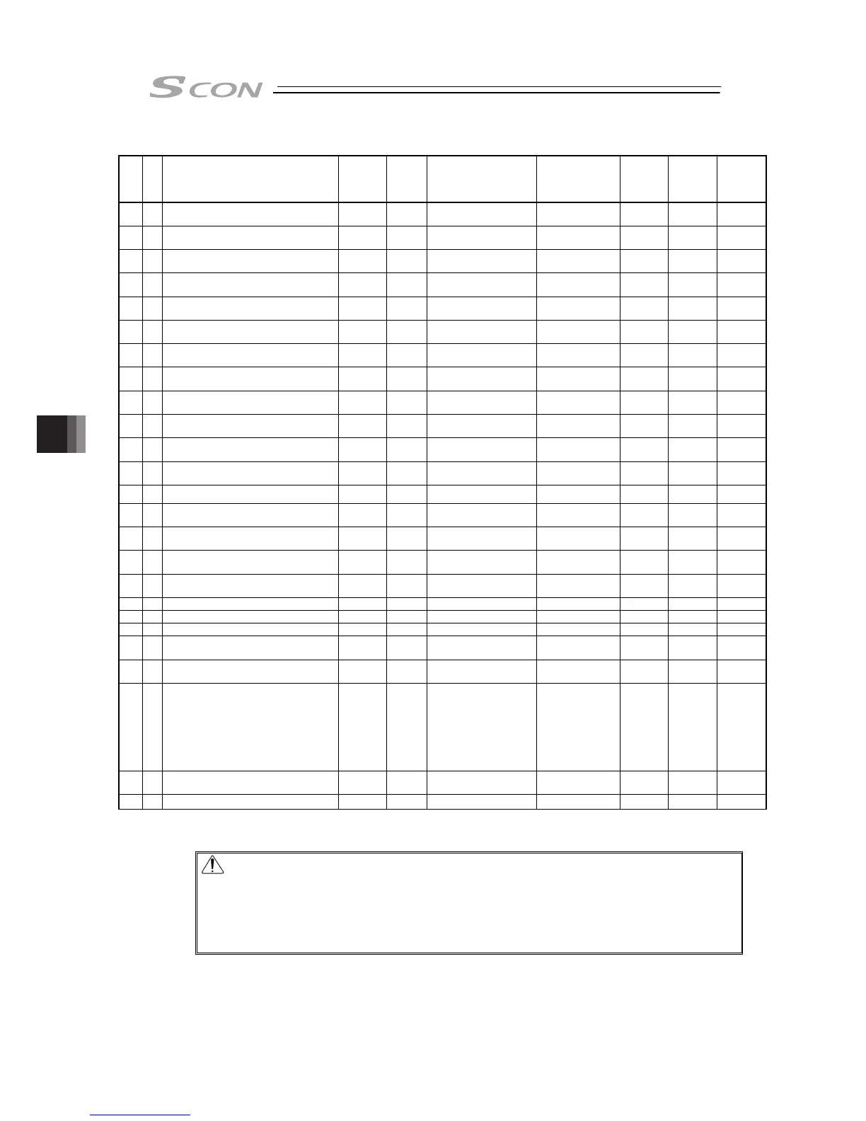
I/O Parameter List (Continued)
No.
Category
Name Symbol Unit Input Range
Default factory
setting
for
Positione
r Mode
for Pulse
Train
Mode
Relevant
sections
126 C Servo gain number 2 PLG2 – 0 to 31
In accordance
with actuator
(Note2)
{
8.2 [5]
8.3
127 C Feed forward gain 2 PLF2 – 0 to 100
In accordance
with actuator
(Note2)
{
8.2 [57]
128 C Velocity Loop Proportional Gain 2 VLG2 – 1 to 27661
In accordance
with actuator
(Note2)
{
8.2 [23]
8.3
129 C Velocity Loop Integral Gain 2 VLT2 – 1 to 217270
In accordance
with actuator
(Note2)
{
8.2 [24]
8.3
130 C Torque Filter Time Constant 2 TRF2 – 0 to 2500
In accordance
with actuator
(Note2)
{
8.2 [25]
8.3
131 C Current control width number 2 CLP2 – 0 to 4
In accordance
with actuator
(Note2)
{
8.2 [40]
8.3
132 C Servo gain number 3 PLG3 – 0 to 31
In accordance
with actuator
(Note2)
{
8.2 [5]
8.3
133 C Feed forward gain 3 PLF3 – 0 to 100
In accordance
with actuator
(Note2)
{
8.2 [57]
134 C Velocity Loop Proportional Gain 3 VLG3 – 1 to 27661
In accordance
with actuator
(Note2)
{
8.2 [23]
8.3
135 C Velocity Loop Integral Gain 3 VLT3 – 1 to 217270
In accordance
with actuator
(Note2)
{
8.2 [24]
8.3
136 C Torque Filter Time Constant 3 TRF3 – 0 to 2500
In accordance
with actuator
(Note2)
{
8.2 [25]
8.3
137 C Current control width number 3 CLP3 – 0 to 4
In accordance
with actuator
(Note2)
{
8.2 [40]
8.3
138 C Servo gain switchover time constant GCFT ms 10 to 2000 10
{
8.2 [108]
139 A Home preset value PRST mm -9999.99 to 9999.99
In accordance
with actuator
(Note2)
{ {
8.2 [109]
140 B IP Address IPAD –
0.0.0.0 to
255.255.255.255
192.168.0.1 –
Separate
volume
141 B Subnet Mask SNMK –
0.0.0.0 to
255.255.255.255
255.255.255.0 –
Separate
volume
142 B Default Gateway DFGW –
0.0.0.0 to
255.255.255.255
0.0.0.0 –
Separate
volume
143 B Overload Caution Load Level Ratio OLWL % 50 to 100 100
{ {
8.2 [113]
147 B Total Movement Count Threshold TMCT Times 0 to 999999999 0 (Disabled)
{
– 8.2 [114]
148 B Total Operated Distance Threshold ODOT m 0 to 999999999 0 (Disabled)
{ {
8.2 [115]
149 B Zone Output Changeover FPIO –
0: Not to change
1: To change
0
{
– 8.2 [116]
150 A Linear Absolute Home Preset Value LAPS mm -9999.99 to 9999.99
In accordance
with actuator
{
8.2 [117]
151 B Light Error Alarm Output Select FSTP – 0:
0: Battery Voltage
Drop Warning
Output
1: Output of
battery voltage
drop warning or
message-level
alarm
{ {
8.2 [118]
159 B FB Half Direct Mode Speed Unit FBVS –
0: 1mm/s unit
1: 0.1mm/s unit
0
{
Separate
volume
165 B Delay Time after Shutdown Release SDDT ms 0 to 10000 0
○
{
8.2 [120]
Note 2: The setting values vary in accordance with the specification of the actuator. At shipment, the
parameters are set in accordance with the specification.
Caution: When the controller is operated via serial communication while SCON-CA
Controller is used, always set the controller in “Positioner Mode” (Piano
Switch 1: Off).
If it happens to be in the “pulse train mode” by mistake, the controller may
operate erratically because it is operated according to the “pulse train mode”
parameters.
 Loading...


