Chapter 1 Specications Check
27
SCON-CA
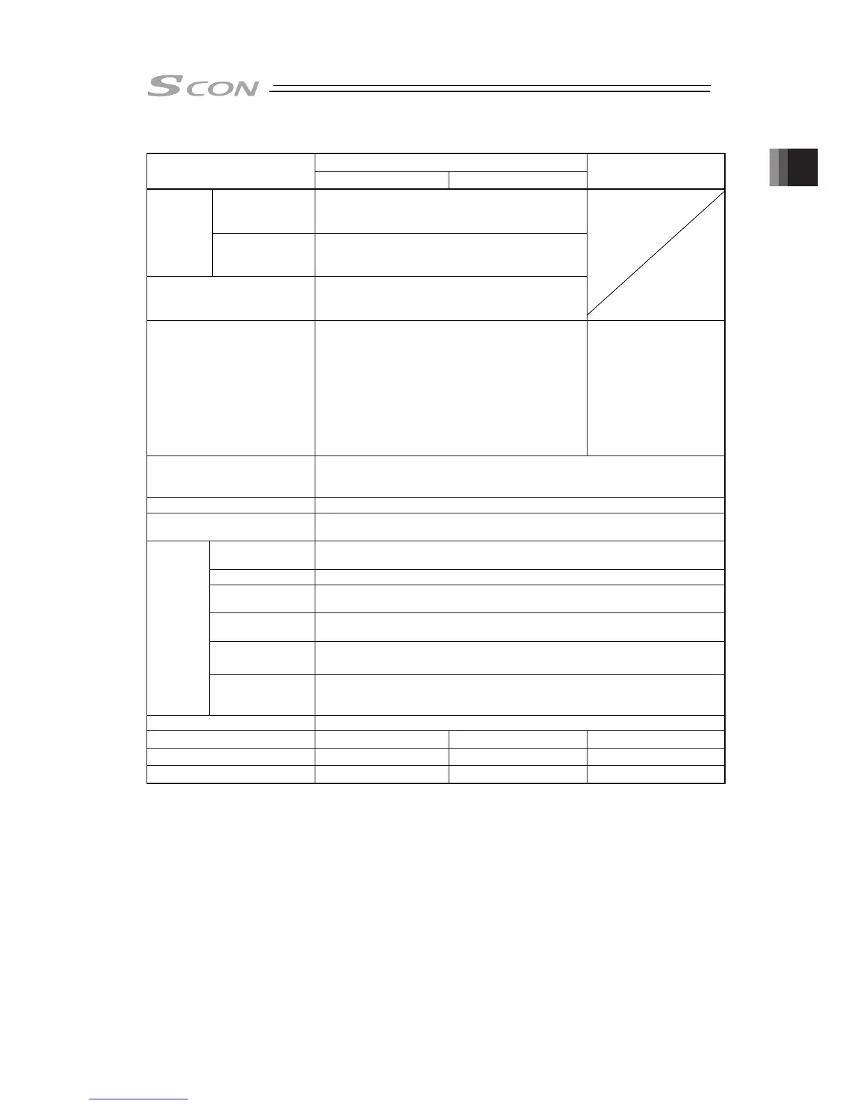
Item
Less than 400W 400W or more
(Note 4)
SCON-CAL/CGAL
Input Pulse
Frequency
Differential System (Line Driver System) : MAX. 2.5Mpps
Open Collector Type : MAX. 200Kpps (under condition
AK-04 is used)
Pulse Train
Interface
(Dedicated
for PIO
Specification)
Command Pulse
Multiplying Factor
(Electrical Gear: A/B)
1/50 < A/B < 50/1
Setting Range of A and B (set to parameter) : 1 to 4096
Feedback Pulse Frequency
(Dedicated for PIO Specification)
Differential System (Line Driver System) : MAX. 2.5Mpps
Open Collector Type : MAX. 500Kpps
(under condition JM-08 is used)
LED Display (mounted on Front
Panel)
PWR (green) : Normal Controller Start,
SV (green) : Servo ON,
ALM (orange) : Alarm Generated,
EMG (red) : Emergency Stop
PWR(green): Normal
Controller
Start,
SV(green): Servo ON,
ALM(orange): Alarm
generated,
EMG(red): Emergency
Stop,
WRG(orange): Warning
generated
Electromagnetic Brake
Compulsory Release
Switch (mounted on Front Panel)
Switching NOM (standard)/BK RLS (compulsory release)
Insulation Resistance 500V DC 10MΩ or more
Insulation Strength 1500V AC for 1 min. (Note) Withstand voltage of pressing operation using force sensor
loadcell is 50V DC
Surrounding air
temperature
0 to 40°C
Surrounding humidity 85%RH or less (should be no condensation or freeze)
Surrounding
environment
[Refer to Installation Environment]
Surrounding storage
temperature
-20 to 70°C (should be no condensation or freeze)
Surrounding storage
humidity
85%RH or less (should be no condensation or freeze)
Environment
Vibration Durability XYZ Each direction 10 to 57Hz Pulsating amplitude 0.035mm (continuous) 0.075mm
(intermittent) 57 to 150Hz 4.9m/s
2
(continuous) 9.8m/s
2
(intermittent)
Protection Class IP20 or equivalent
Weight Approx. 900g Approx. 1200g Approx. 560g
Method Cooling Natural Air-Cooling Forced Air Cooling Forced Air Cooling
External Dimensions 58W × 194H × 121D [mm] 72W × 194H × 121D [mm] 49W × 158H × 116D [mm]
Note 1 In-rush current will flow for approximately 20ms after the power is turned ON (at 40°C).
Note that the value of in-rush current differs depending on the impedance and the internal
element temperature (thermistor type in-rush current control circuit) of the power supply line.
Note 2 Leak current varies depending on the capacity of connected motor, cable length and the surrounding
environment. Measure the leak current at the point where a ground fault circuit interrupter is to be
installed when leakage protection is conducted.
A ground fault circuit interrupter needs to be selected carefully considering the purposes of prevention
of fire and protection of human.
Use the harmonic type (for inverter) for the ground fault circuit interrupter.
Note 3 It is not necessary to supply power to PIO when operating with using ROBONET, Gateway Unit or SIO
Converter without using PIO. In this case, set the parameter No.74 “PIO Power Supply Monitor” to “1”
(Invalid). It will generate the error code No. 0CF “I/O 24V Power Supply Error” if the setting is not done.