7. Handles used for adjusting the chassis placement
8. Grid A PSU bays (1, 2, 5, 6 )
9. Grid B PSU bays (3, 4, 7, 8)
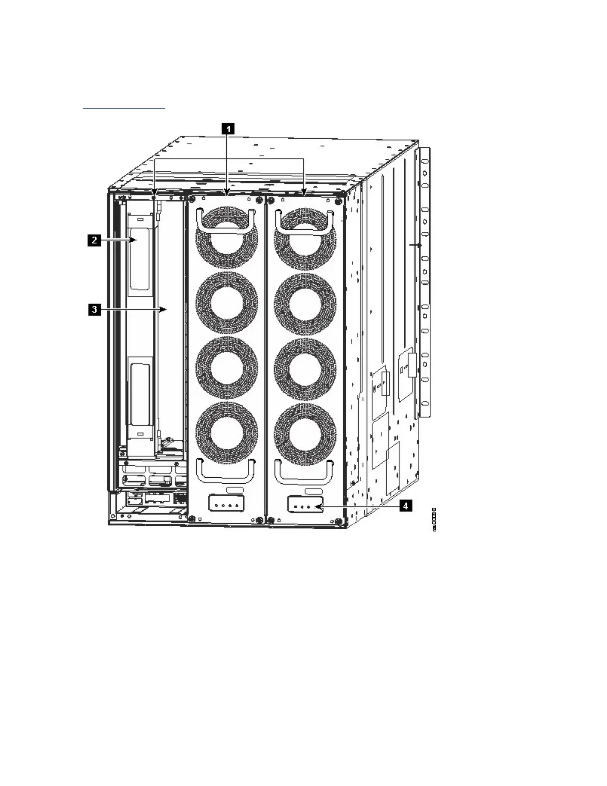
Figure 4 on page 9 shows the rear view of the SAN384C-6 chassis.
Figure 4. SAN384C-6SAN384C-6 Chassis Rear View
1. Fan modules - (Three fan modules) 1-3 are numbered left to the right. When the fan modules are
installed, they cover the crossbar fabric switching modules. Only two fan modules are shown in the
figure. One fan module is removed to show the crossbar fabric switching module in back.
2. Crossbar Fabric Switching Modules - (up to six crossbar fabric switching modules with two modules
behind each fan module). The crossbar fabric switching modules 1 and 2 are behind the fan module
slot 1, modules 3 and 4 are behind the fan module slot 2, and modules 5 and 6 are behind the fan
module slot 3.
3. Midplane
4. Crossbar Fabric Switching Modules and fan LEDs
The SAN384C-6 chassis can be mounted on a standard 19-inch EIA equipment rack by using the standard
rack-mount hardware, or mounted on a standard two-post Telco rack, with mounting rails.
Chapter 1. Introducing the IBM c-type SAN Directors9

 Loading...


