v In a 14U library, over the holes in the rack rails that clip/cage nuts were
installed
e.
Place the screws (
8
in Figure 3-3 on page 3-5) in the slots on the left rack
ear (
7
in Figure 3-3 on page 3-5) and tighten.
3.
Close the I/O Station and Access doors.
4. Repeat this procedure for all modules in the library.
Installing Library Components Removed for Weight Reduction
At this point in the installation procedure, you reinstall the drive sleds and power
supplies that were removed for weight reduction.
Replacing a Drive Sled
Attention: NEVER install a drive sled when a cartridge is in the drive in the eject
position. Remove the cartridge first.
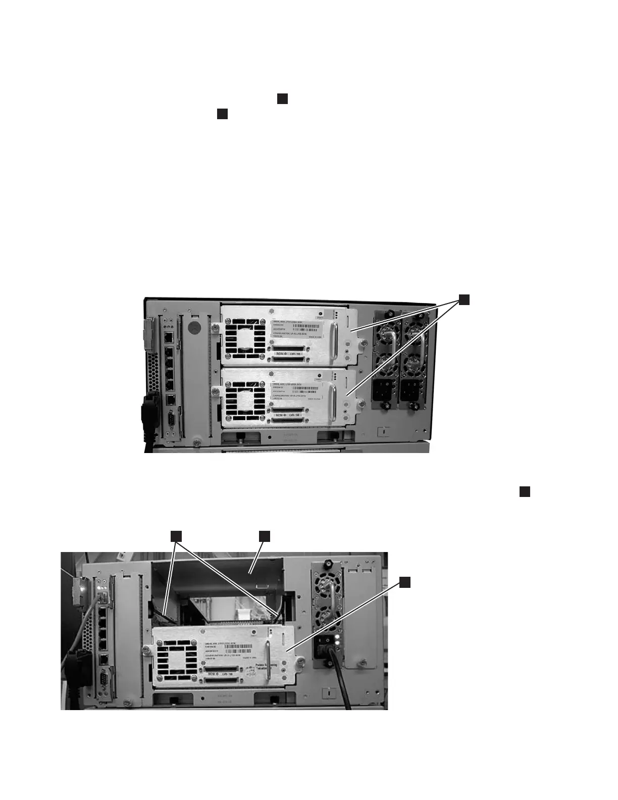
1. Align the drive sled with the guide rails and guide slots along the tracks (
3
in Figure 3-12).
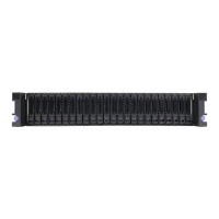
a66ug011
1
Figure 3-11. Control Module Drive Sled
a66ug049
3
1
2
Figure 3-12. Guide rails and guide slots inside a drive slot
3-14 TS3310 Tape Library Setup and Operator Guide