11. Replace the fan cage assembly (see “Replacing the fan cage assembly” on page
173).
12. Replace the top cover (see “Replacing the top cover” on page 147).
13. Slide the server into the rack.
14. Reconnect the power cords and any cables that you removed.
15. Turn on the peripheral devices and the server.
For the left EIA assembly
1. Read the safety information that begins on “Safety” on page vii and
“Installation guidelines” on page 283.
2. Turn off the server and peripheral devices, and disconnect the power cord and
all external cables.
3. Remove the top cover (see “Removing the top cover” on page 146).
4. Remove the fan cage assembly (see “Removing the fan cage assembly” on
page 172).
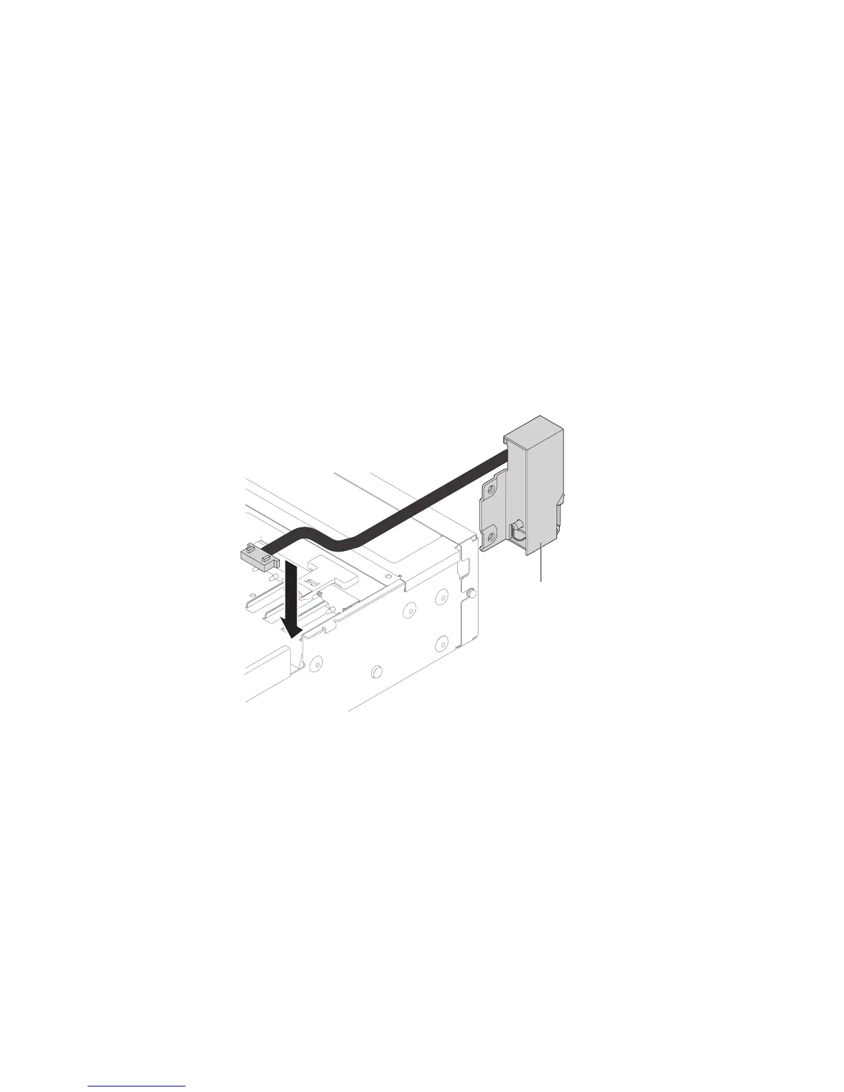
5. Route the cable into the slot.
6. Align the EIA assembly with the alignment pin and push it slightly toward
the rear of the server fix the EIA assembly on the server.
EIA assembly
Figure 162. Cable routing
Chapter 5. Removing and replacing components 219

 Loading...


