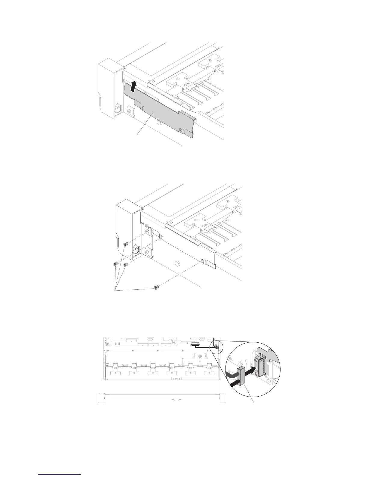
9. Fasten screws.
10. Connect the front USB/operator information panel cables to the system board
and the connector mounted on the chassis side wall.
Cable arm cover
Figure 159. Cable cover installation
Screws
Figure 160. Screw installation
Front USB / operator
information panel cable
Figure 161. Cable connection
218 System x3650 M5 Type 5462: Installation and Service Guide

 Loading...


