3.5-inch model: There are the right EIA assembly and the left EIA assembly on
the server, use the following steps to replace them.
For the right EIA assembly
1. Read the safety information that begins on “Safety” on page vii and
“Installation guidelines” on page 283.
2. Turn off the server and peripheral devices, and disconnect the power cord and
all external cables.
3. Remove the cover (see “Removing the top cover” on page 146).
4. Remove the fan cage (see “Removing the fan cage assembly” on page 172).
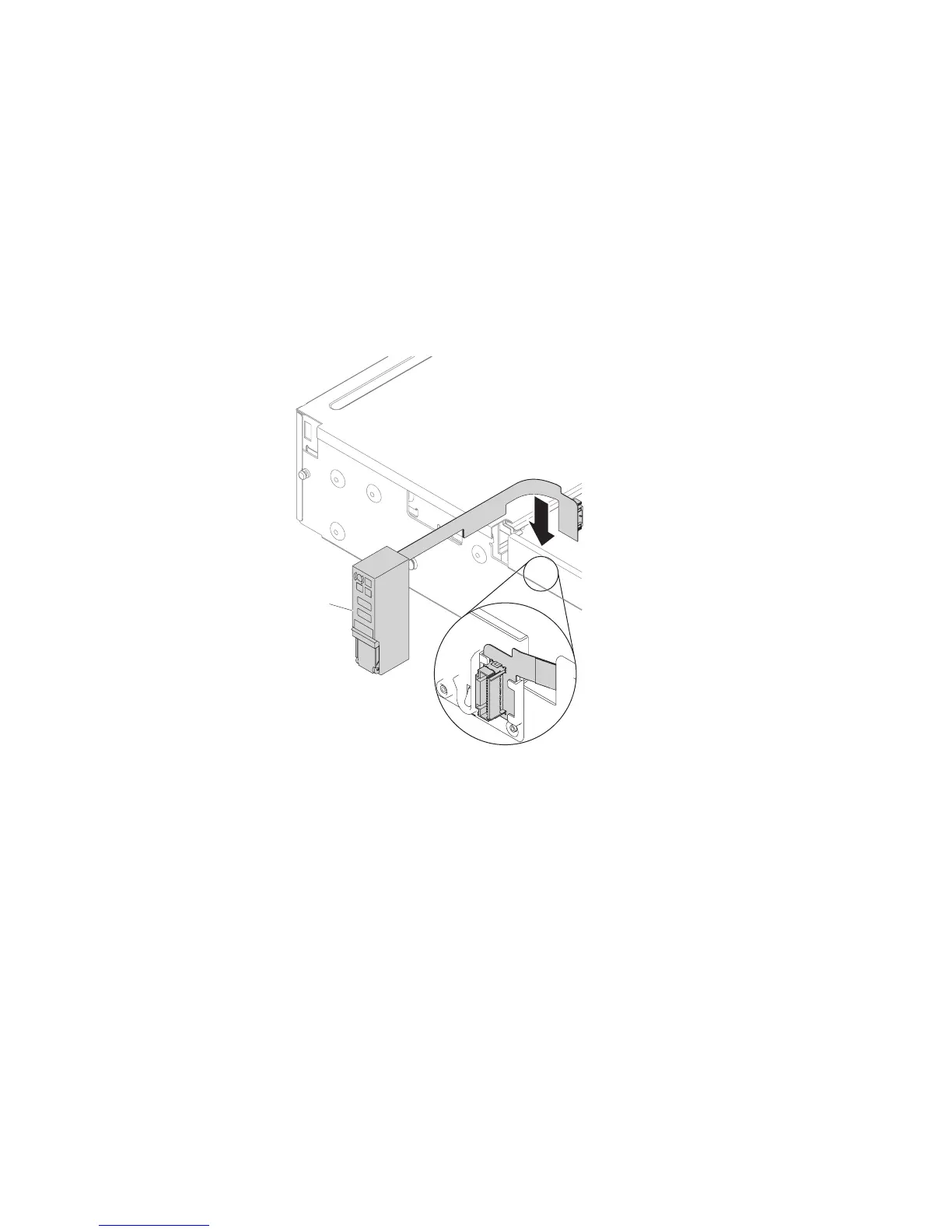
5. Insert the cable connector into the cable connector holder.
6. Align the EIA assembly with the alignment pin.
EIA assembly
Figure 167. Cable connector installation
222 System x3650 M5 Type 5462: Installation and Service Guide

 Loading...


