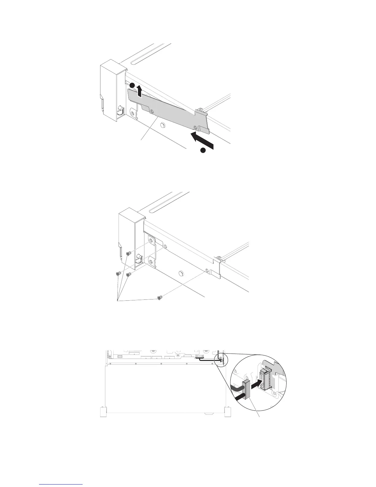
9. Fasten screws.
10. Connect the front USB/operator information panel cables to the system board
and the connector mounted on the chassis side wall.
1
2
Cable arm cover
Figure 170. Cable cover installation
Screws
Figure 171. Screw installation
Front USB / operator
information panel cable
Figure 172. Cable connection
224 System x3650 M5 Type 5462: Installation and Service Guide

 Loading...


