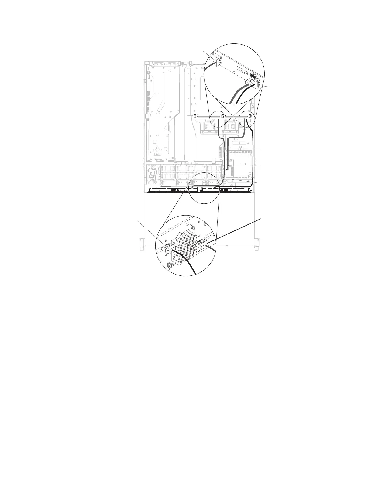
SATA signal cable 0
SATA signal cable 1
SATA 1
SATA 0
SATA 0
SATA 1
Hot-swap backplane
power cable
16. Connect the LED signal cable to the connector which is underneath of the
power connector of the hot-swap backplane. You can temporary remove the
power cable on the hot-swap backplane to make the connection easier.
17. Connect the power cable which you can find near the 240 VA cover into the
backplane assembly on the rear hard disk drive cage (see “Internal cable
routing and connectors” on page 136); then, secure the cables with any
retention clips.
18. Replace the system fan cage:
a. In order to install the fan cage easier, tightly pull the SATA cables to keep
them flat
b. Align the system fan cage with the guide rails on the fan cage bracket.
c. Tilt the fan cage a little bit until it passes the SATA cables. Lower the
system fan cage into the fan cage bracket until the system fan cage clicks
into place.
Chapter 5. Removing and replacing server components 209
 Loading...