12
1
PANEL DESCRIPTION
1
2
3
4
5
6
7
8
9
10
11
12
13
14
15
16
17
18
19
20
21
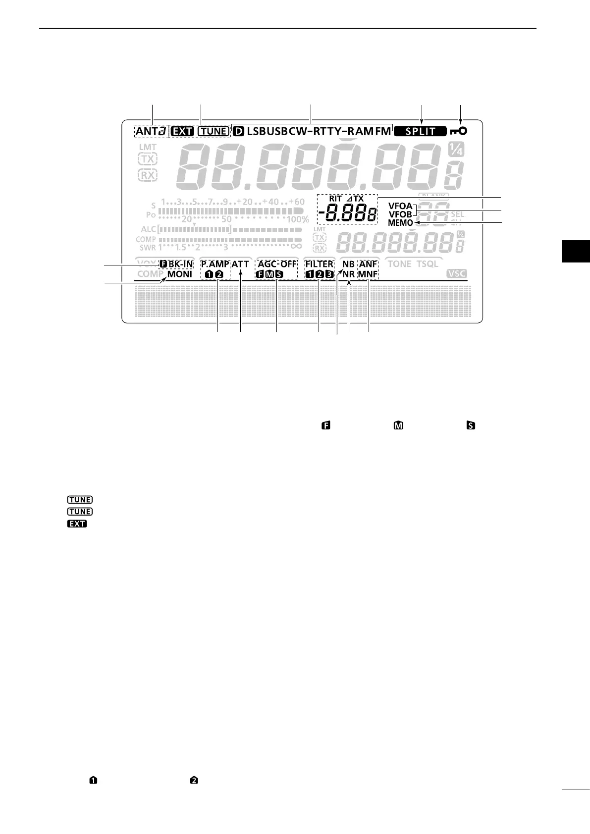
!6 DIAL LOCK ICON (p. 61)
Appears when the Dial Lock function is ON.
!7 SPLIT ICON (p. 66)
Appears when the Split function is ON.
!8 MODE ICONS (p. 31)
Displays the selected operating mode.
•“D” appears when the SSB data, AM data or FM data
mode is selected.
!9 ANTENNA TUNER ICONS (p. 83)
➥“ ” appears when the antenna tuner is ON;
“ ” blinks during tuning.
➥“ ” appears when the optional AH-4 external
antenna tuner is connected to the [ANT1] con-
nector, and [ANT1] is selected.
@0 ANTENNA ICONS (p. 82)
Displays which antenna connector is selected for
HF/50 MHz.
•“ANT1” appears when the [ANT1] connector is se-
lected.
•“ANT2” appears when the [ANT2] connector is se-
lected.
@1 BREAK-IN ICONS (p. 63)
➥“F BK-IN” appears when the Full Break-in func-
tion is ON.
➥“BK-IN” appears when the Semi Break-in func-
tion is ON.
@2 MONITOR ICON (p. 65)
Appears when the Monitor function is ON.
@3 PREAMP ICONS (p. 55)
Appears when a preamplifier is ON.
•“P.AMP ” for preamp 1; “P. AMP ” for preamp 2.
@4 ATTENUATOR ICON (p. 55)
Appears when the Attenuator is ON.
@5 AGC ICONS (p. 56)
Displays the selected AGC time constant.
•“ ” for fast AGC; “ ” for mid AGC; “ ” for slow AGC;
“-OFF” for AGC OFF.
@6 DSP FILTER ICONS (p. 57)
Displays the selected IF filter.
@7 NOISE BLANKER ICON (p. 60)
Appears when the Noise Blanker is ON.
@8 NOISE REDUCTION ICON (p. 61)
Appears when the Noise Reduction is ON.
@9 NOTCH ICONS (p. 61)
(Mode: SSB/CW/RTTY/AM)
➥“MNF” appears when the Manual Notch function
is ON.
(Mode: SSB/AM/FM)
➥“ANF” appears when the Automatic Notch func-
tion is ON.
#0 MEMORY ICON (p. 24)
Appears when the memory mode is selected.
#1 VFO ICONS (p. 24)
Appears when VFO A or VFO B is selected.
#2 RIT/∂TX ICONS (pp. 53, 65)
➥“RIT” appears when the RIT function is ON.
➥“∂TX” appears when the ∂TX function is ON.
➥ Shows the frequency shift of the RIT or ∂TX
function.
@1
@2
@3 @5 @6 @9
@4 @8@7
#0
#1
#2
@0 !9
!7 !6
!8