19
2
INSTALLATION AND CONNECTIONS
■ Power supply connections
When operating the transceiver with AC power, use a
power supply with 13.8 V DC output and a capacity of
at least 23 Amps.
Refer to the diagrams below.
CAUTION: Before connecting the DC power
cable, check the following important items.
Make sure:
•The[POWER]switchisOFF.
•Output voltageof the power sourceis 12–15V
when you use a non-Icom power supply.
•DCpowercablepolarityiscorrect.
Red : Positive + terminal
Black : Negative _ terminal
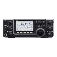
Transceiver
PS-126
AC cable
AC outlet
To [DC 13.8V]
DC power cable
D Connecting to the PS-126 DC POWER SUPPLY
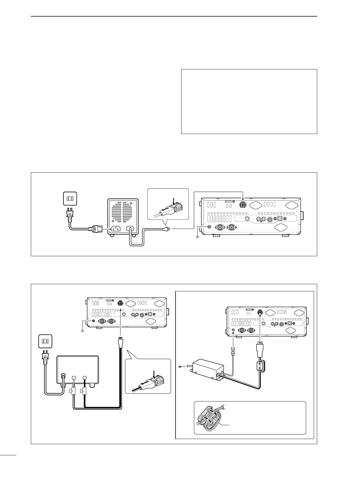
D Connecting to a non-Icom DC POWER SUPPLY
■ Connecting to a DC power supply
Supplied DC power cable
AC cable
AC outlet
Transceiver
To [GND]
A DC power supply
13.8 V;
at least 23 A
Red Black
To [DC 13.8V]
To [DC 13.8V]
For European versions
Transceiver
Connect to
power supply
Ground
Ground
To disconnect
To disconnect
When you install the ferrite
EMI filter, make sure the ca-
bles at the top of the loop are
parallel to each other.