92
1
2
3
4
5
6
7
8
9
12
13
14
16
17
18
19
20
21
DATA COMMUNICATION
15
11
10
11
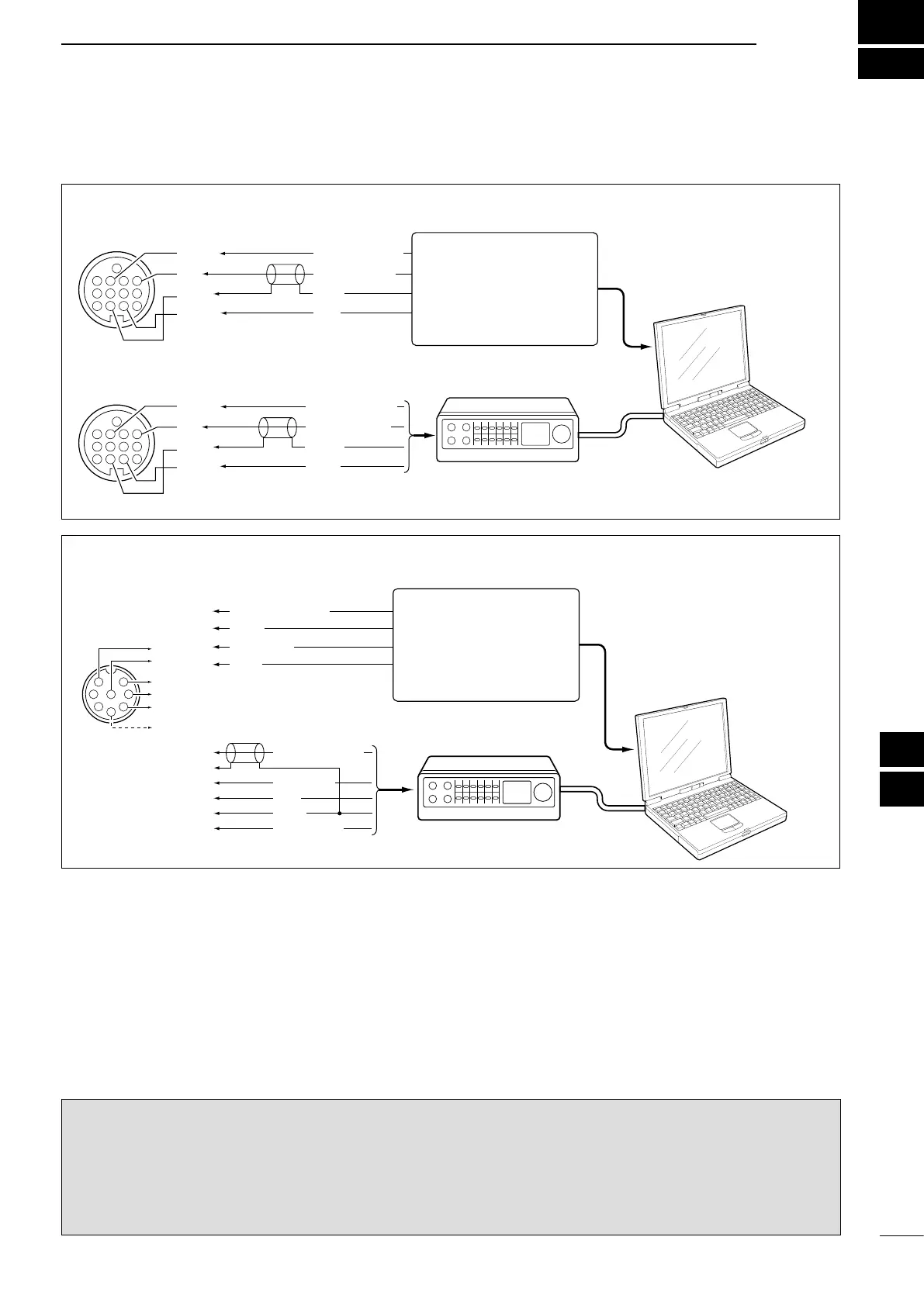
■ Connections
• When using a TNC
• When using a PC application
TNC
PC
RS-232C
Rear panel view
4
8
12
123
765
9
10 11
13
RTTY OUTPUT
AUDIO INPUT
PTT
GND
FSKK
AF
SEND
GND
4
8
12
123
765
9
10 11
13
RTTY OUTPUT
AUDIO INPUT
PTT
GND
FSKK
AF
SEND
GND
q
u
i
t
r
y
AFSK OUTPUT
AF INPUT
PTT
GND
SQL INPUT
• When using a TNC
• When using a PC application
AUDIO OUTPUT
AF INPUT
PTT
GND
q
u
i
t
1
2
3
4
5
6
7
8
q
u
i
t*
1
y
r*
2
Rear panel view
TNC
PC
RS-232C
*
1
When using the VOX func-
tion, no connection is needed.
Refer to the instruction man-
ual of the external equipment.
*
2
When connecting the squelch
line, consult the necessary
manual.
Connect to the serial port,
parallel port, speaker jack,
microphone jack or line IN/
OUT jack, etc.
See the instruction manual
of the application for details.
Connect to the serial port,
parallel port, speaker jack,
microphone jack or line IN/
OUT jack, etc.
See the instruction manual
of the application for details.
INFORMATION!
When the
“
USB Serial Func
” item is set to
“RTTY”
in
the Set mode (p. 89), the USB port sends RTTY decode
signal. In this case, you must connect a USB cable* between the transceiver’s USB port on the rear panel and the
PC. (p. 17)
•TheUSBdriverandtheinstallationguidecanbedownloadedfromourwebsite.
URL: http://www.icom.co.jp/world/index.html
* Purchase separately
D When connecting to [ACC]
D When connecting to [MIC]