16
2
INSTALLATION AND CONNECTIONS
1
2
3
4
5
6
7
8
9
10
11
12
13
14
15
16
17
18
19
20
21
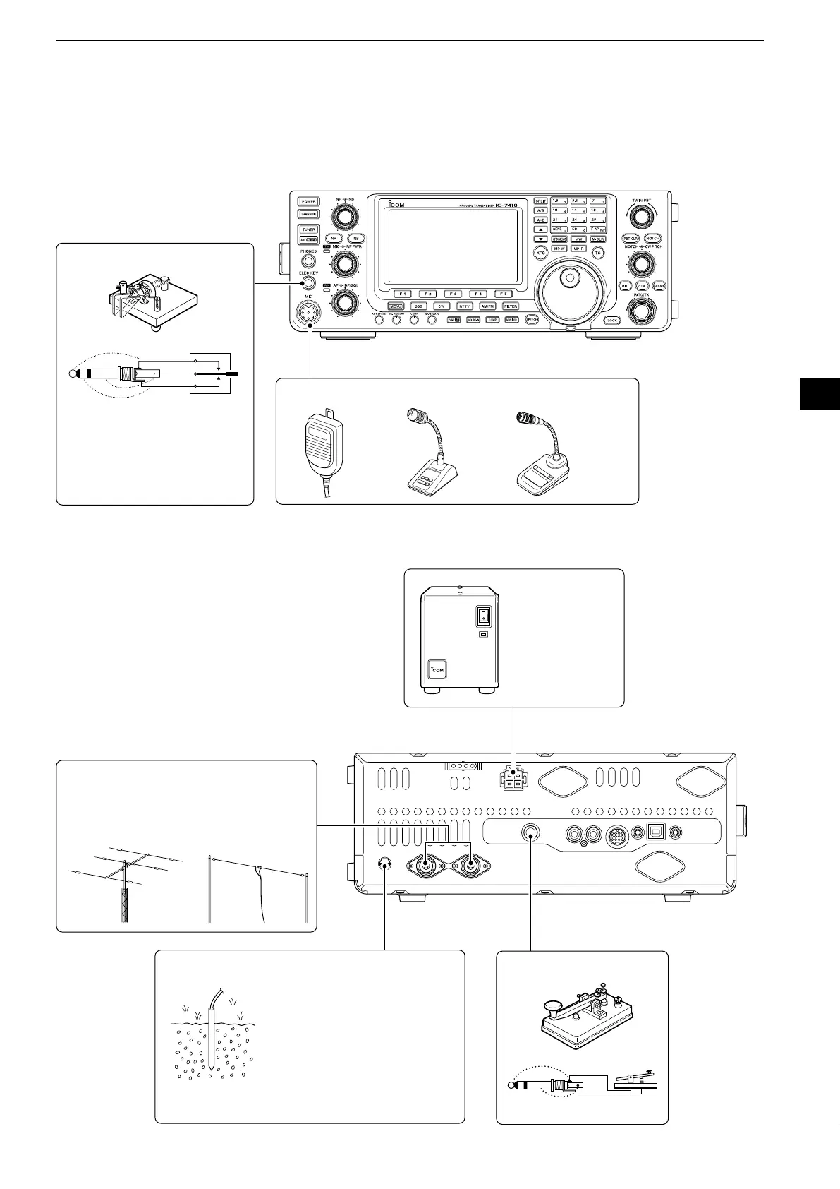
■ Required connections
D Front panel
DC POWER
SUPPLY
(p. 19)
PS-126
Use the heaviest possible
gauge wire or strap and
make the connection as
short as possible.
Grounding prevents elec-
trical shocks, TVI and
other problems.
GROUND (p. 15) STRAIGHT KEY
HF/50MHz ANTENNA 1, 2 (p. 15)
Connection example:
[ANT 1] for 1.8–18 MHz bands antenna
[ANT 2] for 21–28 MHz bands antenna
MICROPHONES (p. 22)
HM-36 SM-30
(option)
ELEC-KEY
A straight key can be con-
nected. However, “Straight
key” must be selected in
the “Keyer Type” item of the
Keyer Set mode. (p. 43)
D Rear panel
SM-50
(option)