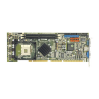
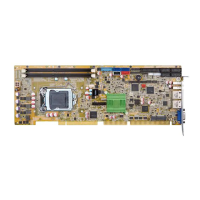
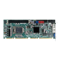
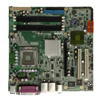
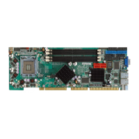
WSB-9454 CPU Card
Page 92
4.7 Chassis Installation
After the CPU, the cooling kit, and the DIMM modules have been installed and after the
internal peripheral connectors have been connected to the peripheral devices and the
jumpers have been configure, the CPU card can be mounted into a chassis.
To mount the CPU card into a chassis please refer to the chassis user guide that came
with the product.
4.8 Rear Panel Connectors
4.8.1 Keyboard and Mouse Connection
A PS/2 keyboard and a PS/2 mouse can be connected to the appropriate PS/2 connector
on the rear panel.
4.8.2 VGA Port Installation
The cable used to connect the motherboard to a VGA port is a 10-pin header to female
HD-D-sub 15 connector. To connect a VGA port to the motherboard, follow the
instructions below.
Step 1: Connect a standard male HD-D-sub 15 connector end to the VGA connector on
the rear panel.
Step 2: Connect the other end to a display device. Step 0:
4.8.3 Ethernet Connection
The rear panel RJ-45 connectors can be connected to an external LAN and communicate
with data transfer rates up to 1Gb/s.
 Loading...
