Home
IEI Technology
Motherboard
WSB-9454
IEI Technology WSB-9454 User Manual
5
of 1
of 1 rating
234 pages
Give review
Manual
Specs
To Next Page
To Next Page
To Previous Page
To Previous Page
Loading...
WSB-9454 CPU Card
Page 80
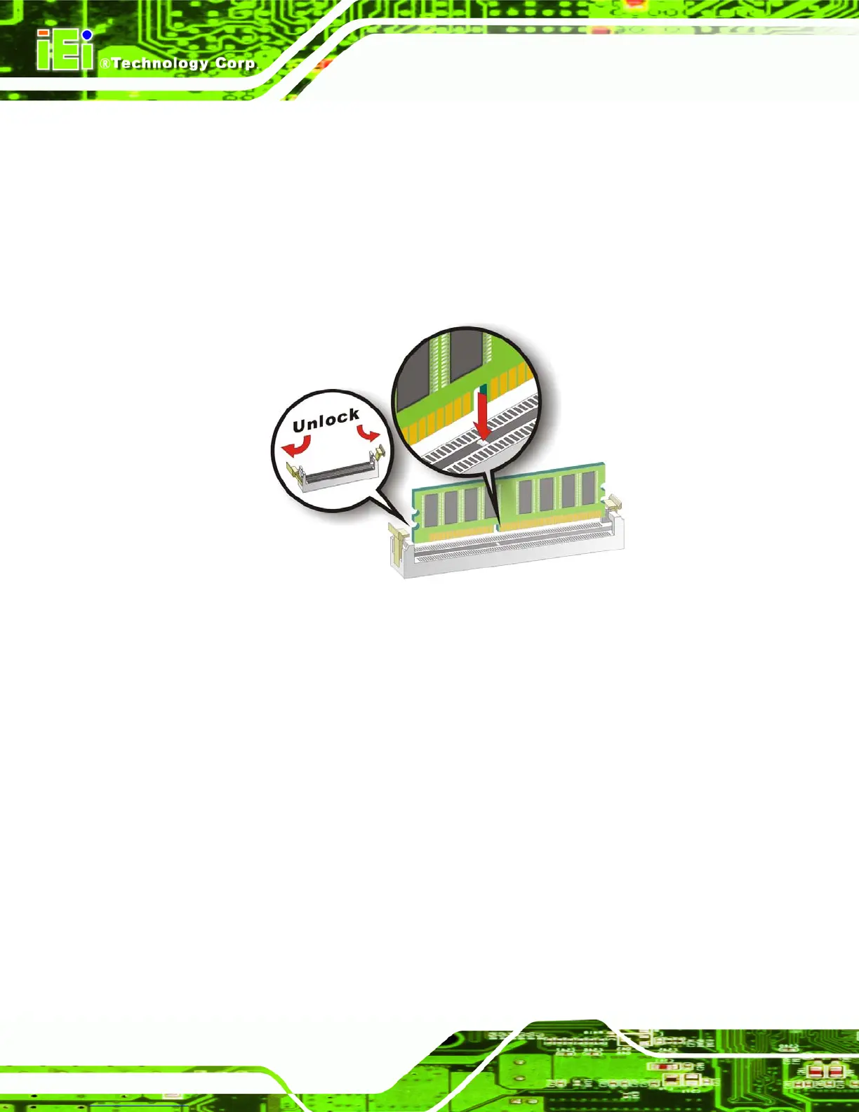
4.5.3.2 DIMM Module Inst
allation
The WSB-9454 CPU card has four 240
-pin DD
R2 SDRAM DIMM
socket
s. To install the
DIMM modules, follow the instructions b
elow.
Step 1:
Make sure the two handles of the DIMM
socket are
in the "open" position,
leaning outward (
Figure 4-7
).
Figure 4-7: Installing the DIMM Module
95
97
Table of Contents
Table of Contents
3
Default Chapter
2
Revision History
2
This Page Is Intentionally Left Blank
16
1 Introduction
17
Wsb-9454 Cpu Card Overview
18
Table 1-1: WSB-9454 Model Variations
18
WSB-9454 CPU Card Applications
18
WSB-9454 CPU Card Benefits
18
WSB-9454 Model Variations
18
WSB-9454 CPU Card Features
19
Wsb-9454 Cpu Card Overview
20
Table 1-2: WSB-9454 CPU Card Overview
20
WSB-9454 CPU Card Connectors
21
Technical Specifications
22
Table 1-3: Technical Specifications
24
2 Detailed Specifications
25
Compatible Iei Backplanes
26
Cpu Support
26
Intel ® Core™ Duo
26
Table 2-1: Supported Cpus
26
Intel ® Pentium ® 4
27
Intel ® Pentium ® D
27
Intel ® Celeron ® D
28
On-Board Chipsets
28
Intel ® 945G Northbridge Chipset
28
Northbridge and Southbridge Chipsets
28
Intel ® ICH7 Southbridge Chipset
29
Graphics Support
30
Analog VGA
30
Intel ® GMA 950
30
Digital Visual Interface (DVI)
31
Data Flow
32
Figure 2-1: Data Flow Block Diagram
32
Memory Support
33
Pci Bus Interface Support
33
Gbe Ethernet Connection
33
Drive Interfaces
34
Floppy Disk Drive (FDD)
35
IDE HDD Interfaces
35
SATA Drives
35
Serial Ports
36
Real Time Clock
36
System Monitoring
36
Infrared Data Association (Irda) Interface
36
Bios
37
Operating Temperature and Temperature Control
37
Optional Audio Interface
37
Power Consumption
38
Packaged Contents and Optional Accessory Items
38
Package Contents
38
Special Items
38
Table 2-2: Power Consumption
38
Optional Accessory Items
39
3 Connectors and Jumpers
41
Peripheral Interface Connectors
42
WSB-9454 CPU Card Layout
42
Figure 3-1: Connector and Jumper Locations
43
Peripheral Interface Connectors
44
External Peripheral Interface Connectors
45
Table 3-1: Peripheral Interface Connectors
45
Table 3-2: External Peripheral Interface Connectors
45
On-Board Jumper
46
Internal Peripheral Connectors
46
ATX-12V Power Source Connector
46
Table 3-3: On-Board Jumper
46
Figure 3-2: ATX-12V Connector Location
47
Table 3-4: ATX-12V Connector Pinouts
47
Audio Module Connector
48
Figure 3-3: Audio Module Connector Location
49
Backplane to Mainboard Power Connector
50
Table 3-5: Audio Module Connector Pinouts
50
Figure 3-4: Backplane to Mainboard Power Connector Location
51
Table 3-6: Backplane to Mainboard Power Pinouts
51
CPU Fan Connector
52
Figure 3-5: CPU Fan Connector Location
53
Table 3-7: CPU Fan Connector Pinouts
53
Digital Input/Output (DIO) Connector
54
Figure 3-6: DIO Connector Location
55
DVI (Digital Visual Interface) Connector
56
Table 3-8: DIO Connector Pinouts
56
Figure 3-7: DVI Connector Location
57
FDD Connector
58
Table 3-9: DVI Connector Pinouts
58
Figure 3-8: FDD Connector Location
59
Front Panel Connector
60
Table 3-10: FDD Connector Pinouts
60
Figure 3-9: Front Panel Connector Location
61
IDE Connector
62
Table 3-11: Front Panel Connector Location
62
Figure 3-10: IDE Connector Location
63
Table 3-12: IDE Connector Pinouts
64
Irda Interface Connector
65
Figure 3-11: Irda Interface Connector Location
66
Keyboard Connector
67
Table 3-13: Irda Interface Connector Pinouts
67
Figure 3-12: Keyboard Connector Location
68
Parallel Port Connector
69
Table 3-14: KB1 Connector Pinouts
69
Figure 3-13: Parallel Port Connector Location
70
Serial Port Connectors
71
Table 3-15: Parallel Port Connector Pinouts
71
Figure 3-14: RS-232 Serial Port Connectors Location
72
SATA Drive Connectors
73
Table 3-16: RS-232 Serial Port Connectors Pinouts
73
Figure 3-15: SATA Connectors Location
74
Table 3-17: SATA Connectors Pinouts
74
USB Connectors
76
Figure 3-16: USB Port Connector Location
77
External Peripheral Interface Connectors
78
Figure 3-17: External Peripheral Interface Connector Panel
78
Table 3-18: USB Port Connector Pinouts
78
Figure 3-18: RJ-45 Ethernet Connector
79
LAN Connectors
79
Table 3-19: LAN Pinouts
79
Figure 3-19: Mini-DIN 6 PS/2 Connector
80
Mini-DIN 6 PS/2 Connector
80
Table 3-20: RJ-45 Ethernet Connector Leds
80
Table 3-21: Mini-DIN 6 PS/2 Connector
81
Table 3-22: USB Port Pinouts
81
USB Connector
81
Figure 3-20: VGA Connector
82
Table 3-23: VGA Connector Pinouts
82
VGA Connector
82
4 Installation and Configuration
83
Anti-Static Precautions
84
Installation Considerations
84
Installation Notices
84
Unpacking
85
Unpacking Precautions
85
Checklist
86
Wsb-9454 Cpu Card Installation
87
Socket Lga775 Cpu Installation
88
CPU Installation
88
CPU Selection: HT Functionality Requirements
88
Figure 4-1: Intel ® LGA775 Socket
89
Figure 4-2: Remove the CPU Socket Protective Shield
90
Figure 4-3: Open the CPU Socket Load Plate
90
Figure 4-4: Insert the Socket LGA775 CPU
91
Figure 4-5: IEI LGA-775 Cooling Kit
92
Socket LGA775 Cooling Kit (CF-520) Installation
92
Figure 4-6: Securing the Heat Sink to the PCB
94
DIMM Module Installation
95
Purchasing the Memory Module
95
DIMM Module Installation
96
Figure 4-7: Installing the DIMM Module
96
Peripheral Device Connection
97
Table 4-1: IEI Provided Cables
97
IDE Drive Connector (PIDE1)
98
Figure 4-8: Connection of IDE Connector
99
Floppy Drive Connector (FDD1)
100
SATA Drive Connection
100
Figure 4-9: SATA Drive Cable Connection
101
Figure 4-10: SATA Drive Connection
102
Installing the RS-232 Cable
102
Figure 4-11: Dual RS-232 Cable Installation
103
USB 2.0 Cable Connection
103
Figure 4-12: USB Cable Installation
104
On-Board Jumper
105
Figure 4-13 Jumper
105
Table 4-2: On-Board Jumpers
105
Figure 4-14: Jumper Locations
106
Clear CMOS Jumper
107
Table 4-3: Clear CMOS Jumper Settings
107
Chassis Installation
108
Rear Panel Connectors
108
Ethernet Connection
108
Keyboard and Mouse Connection
108
VGA Port Installation
108
USB Connection
109
5 Ami Bios Setup
111
Introduction
112
Starting Setup
112
Using Setup
112
BIOS Menu Bar
113
Getting Help
113
Table 5-1: BIOS Navigation Keys
113
Unable to Reboot after Configuration Changes
113
Main
114
BIOS Menu 1: Main
114
System Overview
114
Advanced
115
BIOS Menu 2: Advanced
116
CPU Configuration
117
BIOS Menu 3: CPU Configuration
117
IDE Configuration
118
BIOS Menu 4: IDE Configuration
118
ATA/IDE Configuration [Compatible]
118
IDE Master and IDE Slave
119
Legacy IDE Channels [SATA Pri, PATA Sec]
119
IDE Master, IDE Slave
120
BIOS Menu 5: IDE Master and IDE Slave Configuration
120
Lba/Large Mode [Auto]
121
Type [Auto]
121
Zip
121
Block (Multi Sector Transfer) [Auto]
122
PIO Mode [Auto]
122
32Bit Data Transfer [Enabled]
123
Auto
123
DMA Mode [Auto]
123
Floppy Configuration
124
BIOS Menu 6: Floppy Configuration
124
Super IO Configuration
125
BIOS Menu 7: Super IO Configuration
125
Floppy A/B [1.44 MB 3½"]
125
On-Board Floppy Controller [Enabled]
126
Serial Port1 Address [3F8/IRQ4]
126
Serial Port2 Address [2F8/IRQ3]
127
Serial Port2 Mode [Normal]
127
Parallel Port Address [378]
128
Parallel Port Mode [Normal]
128
Parallel Port IRQ [IRQ7]
129
Hardware Health Configuration
130
BIOS Menu 8: Hardware Health Configuration
130
CPU FAN Mode Setting: [Manual Mode]
131
CPUFAN0 PWM Control
131
CPUFAN0 Startup Value
131
CPUFAN0 Stop Value
131
CPUFAN0 Stoptime Value
131
CPUFAN0 Targettemp Value
131
CPUFAN0 Tolerance Value
131
CPUFAN0 Stoptime Value
132
CPUFAN0 Targetspeed Value
132
CPUFAN0 Tolerance Value
132
ACPI Configuration
133
BIOS Menu 9: ACPI Configuration
133
ACPI Aware O/S [Yes]
133
General ACPI Configuration
134
BIOS Menu 10: General ACPI Configuration
134
Repost Video on S3 Resume [Yes]
135
Suspend Mode [Auto]
135
APM Configuration
136
BIOS Menu 11: APM Configuration
136
Power Management/Apm [Enabled]
136
Power Button Mode [On/Off]
137
Resume on Ring [Disabled]
137
Resume on RTC Alarm [Disabled]
137
RTC Alarm Date (Days)
138
RTC Alarm Time
138
MPS Configuration
139
BIOS Menu 12: MPS Configuration
139
MPS Revision [1.4]
139
USB Configuration
140
BIOS Menu 13: USB Configuration
140
Legacy USB Support [Enabled]
140
USB Devices Enabled
140
Port 64/60 Emulation [Disabled]
141
USB2.0 Controller Mode [Hispeed]
141
BIOS EHCI Handoff [Enabled]
142
Pci/Pnp
142
BIOS Menu 14: Pci/Pnp Configuration
144
Clear NVRAM [No]
144
PCI Latency Timer [64]
145
Plug & Play O/S [No]
145
Allocate IRQ to PCI VGA [Yes]
146
Palette Snooping [Disabled]
146
Offboard PCI/ISA IDE Card [Auto]
147
PCI IDE Busmaster [Enabled]
147
IRQ# [Available]
148
DMA Channel# [Available]
149
Reserved Memory Size [Disabled]
149
Boot
150
BIOS Menu 15: Boot
150
Boot Settings Configuration
151
BIOS Menu 16: Boot Settings Configuration
151
Addon ROM Display Mode [Force BIOS]
151
Quick Boot [Enabled]
151
Bootup Num-Lock [On]
152
Boot Device Priority
153
PS/2 Mouse Support [Auto]
153
BIOS Menu 17: Boot Device Priority Settings
154
Removable Drives
155
BIOS Menu 18: Removable Drives
156
Security
157
BIOS Menu 19: Security
157
Change Supervisor Password
157
Boot Sector Virus Protection [Disabled]
158
Change User Password
158
Chipset
159
BIOS Menu 20: Chipset
159
Northbridge Configuration
160
BIOS Menu 21: Northbridge Chipset Configuration
160
DRAM Frequency [Auto]
160
Configure DRAM Timing by SPD [Enabled]
161
Memory Hole [Disabled]
161
Initiate Graphic Adapter [PEG/PCI]
162
Internal Graphics Mode Select [Enabled, 8MB]
162
Video Function Configuration
163
BIOS Menu 22: Video Function Configuration
163
DVMT Mode Select [DVMT Mode]
163
DVMT/FIXED Memory [128MB]
164
Southbridge Configuration
165
BIOS Menu 23:Southbridge Chipset Configuration
165
Audio Controller [Auto]
166
Onboard LAN1 [Auto]
166
Onboard LAN2 [Auto]
166
Onboard Lan Rom [Disabled]
167
Exit
168
BIOS Menu 24:Exit
168
Discard Changes
168
Discard Changes and Exit
168
Save Changes and Exit
168
Load Failsafe Defaults
169
Load Optimal Defaults
169
6 Software Drivers
171
Available Software Drivers
172
Chipset Driver Installation
172
Figure 6-1: Installshield Wizard Preparation Screen
173
Figure 6-2: Welcome Screen
173
Figure 6-3: License Agreement
174
Figure 6-4: Readme Information
175
Figure 6-5: Restart the Computer
176
Vga Driver
177
Figure 6-6: Starting Install Shield Wizard Screen
177
Figure 6-7: Preparing Setup Screen
178
Figure 6-8: VGA Driver Installation Welcome Screen
179
Figure 6-9: VGA Driver License Agreement
180
Figure 6-10: VGA Driver Installing Notice
180
Figure 6-11: VGA Driver Installation Complete
181
Broadcom LAN Driver (for Gbe LAN) Installation
182
Figure 6-12: Access Windows Control Panel
182
Figure 6-13: Double Click the System Icon
183
Figure 6-14: Double Click the Device Manager Tab
184
Figure 6-15: Device Manager List
184
Figure 6-16: Search for Suitable Driver
185
Figure 6-17: Locate Driver Files
186
Figure 6-18: Location Browsing Window
187
Realtek Ac `97 (Alc655) Audio Driver Installation
188
BIOS Setup
188
Driver Installation
188
Figure 6-19: CD 4-AUDIO\AC-Kit08R\Windows Folder
189
Figure 6-20: AC`97 Audio Driver Install Shield Wizard Starting
189
Figure 6-21: AC`97 Audio Driver Setup Preparation
190
Figure 6-22: AC`97 Audio Driver Welcome Screen
191
Figure 6-23: AC`97 Audio Driver Software Configuration
192
Figure 6-24: AC`97 Audio Driver Digital Signal
193
Figure 6-25: AC`97 Audio Driver Installation Begins
194
Figure 6-26: AC`97 Audio Driver Installation Complete
195
Bios Configuration Options
197
A.1 BIOS Configuration Options
198
Default Chapter
198
Bios Configuration Ptions
198
O Ptions
198
Bdio Connector
201
Dio Interface Introduction
202
Dio Connector Pinouts
202
Assembly Language Samples
203
Enable the DIO Input Function
203
Enable the DIO Output Function
203
Cwatchdog Timer
205
Daddress Mapping
209
Io Address Map
210
St Mb Memory Address Map
211
Irq Mapping Table
211
Dma Channel Assignments
211
Addres Map
211
Eexternal Ac'97 Audio Codec
213
Introduction
214
Physical Connection
216
Driver Installation
216
Sound Effect Configuration
218
Sound Effect
219
Environment Simulation
219
Karaoke Mode
221
Equalizer Selection
222
Speaker Configuration
223
Speaker Test
224
S/PDIF-In & S/PDIF-Out
225
Connector Sensing
226
Hrtf Demo
229
Microphone Effect
229
E.13 HRTF Demo
229
General
230
E.15 G Eneral
230
Index
231
Other manuals for IEI Technology WSB-9454
Quick Installation Guide
10 pages
5
Based on 1 rating
Ask a question
Give review
Questions and Answers:
Need help?
Do you have a question about the IEI Technology WSB-9454 and is the answer not in the manual?
Ask a question
IEI Technology WSB-9454 Specifications
General
Brand
IEI Technology
Model
WSB-9454
Category
Motherboard
Language
English
Related product manuals
IEI Technology WSB-9150
3 pages
IEI Technology WSB-H810
165 pages
IEI Technology WAFER-LX-800-R12
227 pages
IEI Technology PCIE-Q57A
159 pages
IEI Technology KINO-9454
209 pages
IEI Technology IMB-9454G-R20
172 pages
IEI Technology IMBA-8650
248 pages
IEI Technology PCISA-6770-RS
8 pages
IEI Technology KINO-6612
11 pages
IEI Technology KINO-9452
199 pages

 Loading...


