WSB-9454 CPU Card
Page 62
PIN DESCRIPTION PIN DESCRIPTION
1 VCC 2 GND
3 DATA- 4 DATA+
5 DATA+ 6 DATA-
7 GND 8 VCC
Table 3-18: USB Port Connector Pinouts
3.3 External Peripheral Interface Connectors
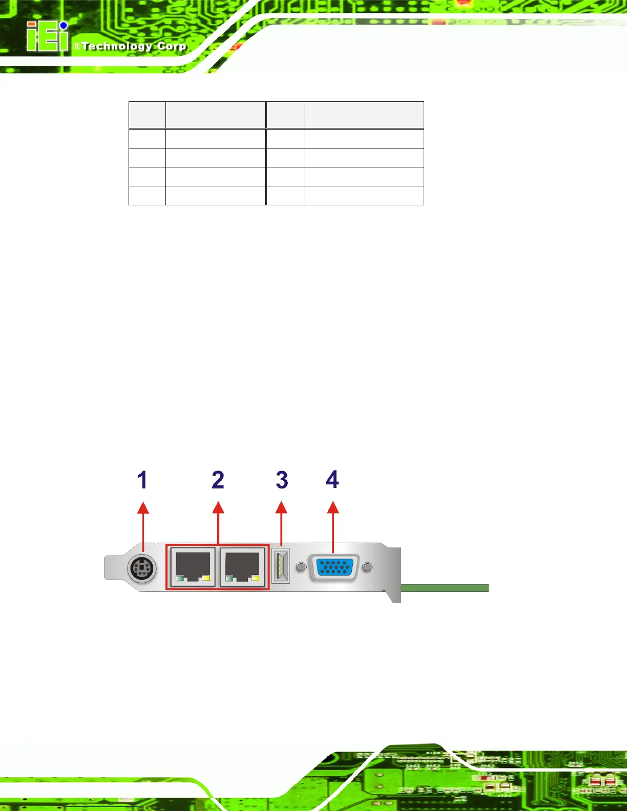
Figure 3-17 shows the WSB-9454 CPU card rear panel. The peripheral connectors on the
back panel can be connected to devices externally when the CPU card is installed in a
chassis. The peripheral connectors on the rear panel are:
1 x PS/2 keyboard connector
1 x USB connectors
2 x RJ-45 GbE connectors
1 x VGA connector
Figure 3-17: External Peripheral Interface Connector Panel

 Loading...


