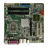
WSB-9454 CPU Card
Page ix
List of Figures
Figure 2-1: Data Flow Block Diagram........................................................................16
Figure 3-1: Connector and Jumper Locations .........................................................27
Figure 3-2: ATX–12V Connector Location ................................................................31
Figure 3-3: Audio Module Connector Location ........................................................33
Figure 3-4: Backplane to Mainboard Power Connector Location ..........................35
Figure 3-5: CPU Fan Connector Location.................................................................37
Figure 3-6: DIO Connector Location .........................................................................39
Figure 3-7: DVI Connector Location..........................................................................41
Figure 3-8: FDD Connector Location ........................................................................43
Figure 3-9: Front Panel Connector Location............................................................45
Figure 3-10: IDE Connector Location........................................................................47
Figure 3-11: IrDA Interface Connector Location ......................................................50
Figure 3-12: Keyboard Connector Location .............................................................52
Figure 3-13: Parallel Port Connector Location.........................................................54
Figure 3-14: RS-232 Serial Port Connectors Location ............................................56
Figure 3-15: SATA Connectors Location ..................................................................58
Figure 3-16: USB Port Connector Location..............................................................61
Figure 3-17: External Peripheral Interface Connector Panel ..................................62
Figure 3-18: RJ-45 Ethernet Connector ....................................................................63
Figure 3-19: Mini-DIN 6 PS/2 Connector ...................................................................64
Figure 3-20: VGA Connector ......................................................................................66
Figure 4-1: Intel
®
LGA775 Socket ..............................................................................73
Figure 4-2: Remove the CPU Socket Protective Shield...........................................74
Figure 4-3: Open the CPU Socket Load Plate...........................................................74
Figure 4-4: Insert the Socket LGA775 CPU...............................................................75
Figure 4-5: IEI LGA-775 Cooling Kit ..........................................................................76
Figure 4-6: Securing the Heat sink to the PCB.........................................................78
Figure 4-7: Installing the DIMM Module ....................................................................80
 Loading...
