P.O. BOX 390 Tel.: +47 51 96 17 00 post@innova.no
4067 Stavanger, Norway Fax.: +47 51 96 17 01 www.innova.no
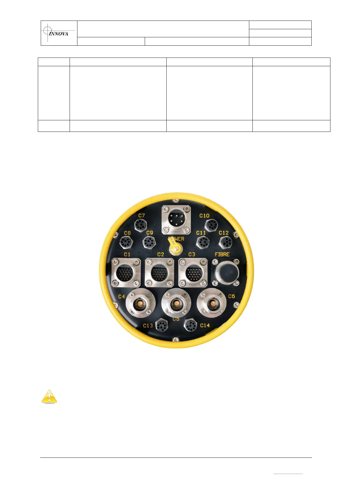
Interfacing details of each connector, including pinout for each connector topside and
subsea are found in Appendix A. Please refer to this section for making appropriate
interface cables.
Figure 5 – Standard connector layout
Important: Do not apply power to any of the outputs before the outputs have been
configured according to the sensors connected to each output. Refer to section 3.4.3
for instructions on how to configure the outputs.
On the back side of the topside unit, the connectors for the different data channels are marked
with numbers reflecting the matching subsea connector. For example, the data channels found in
C1 on the subsea unit (Ethernet and serial), are accessed on the topside unit at the connectors
marked "C1" or "1".
 Loading...