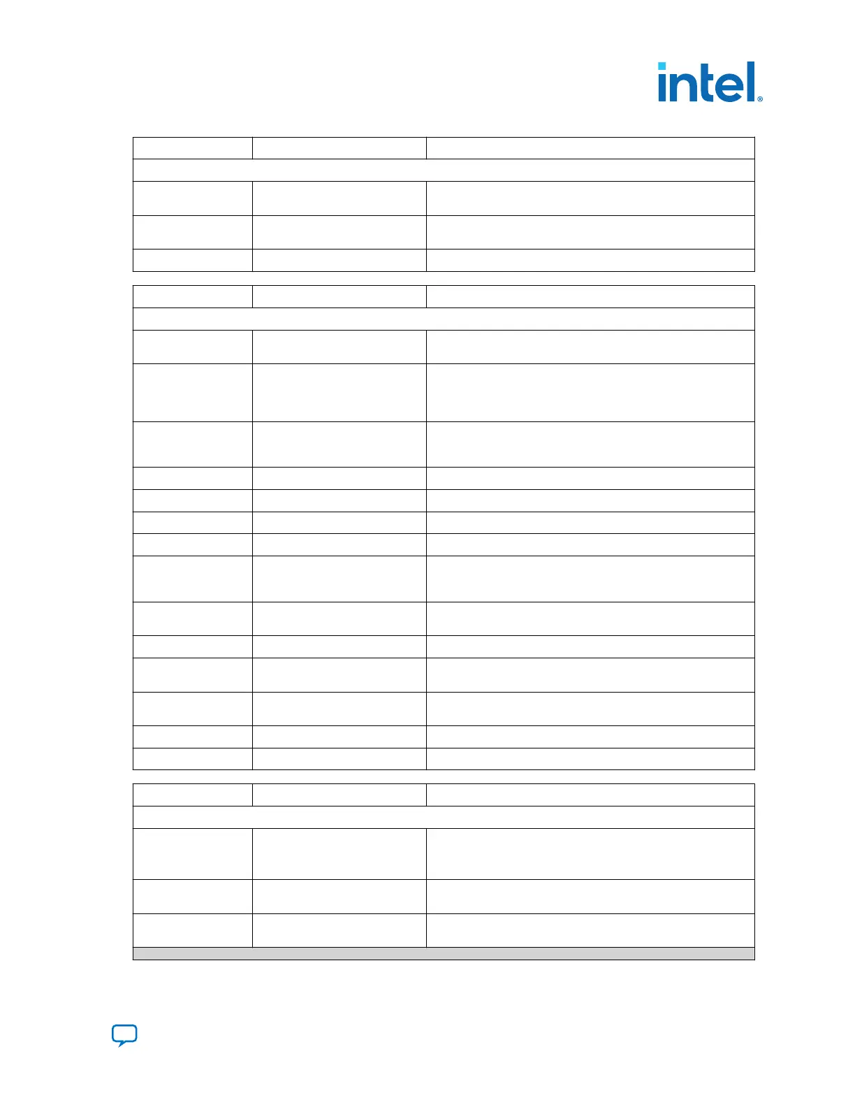
Board Reference Type Description
Configuration and Setup Elements
S5 Image select push button Toggles the configuration LEDs which selects the program
image that loads from flash memory to the FPGA.
S6 Program configuration push
button
Configures the FPGA from flash memory image based on the
program LEDs.
S7 MAX V reset push button The default reset for the MAX V CPLD System Controller.
Board Reference Type Description
Status Elements
D22, D23 JTAG LEDs Indicates transmit or receive activity of the JTAG chain. The TX
and RX LEDs flicker if the link is in use and active.
D24, D25 System Console LEDs Indicates the transmit or receive activity of the System Console
USB interface. The TX and RX LEDs would flicker if the link is in
use and active. The LEDs are either off when not in use or on
when in use but idle.
D12, D13, D14 Program LEDs Illuminates to show the LED sequence that determines which
flash memory image loads to the FPGA when you press the
program load push button.
D17 Configuration done LED Illuminates when the FPGA is configured.
D15 Load LED Illuminates during FPGA configuration.
D16 Error LED Illuminates when the FPGA configuration from flash fails.
D19 Power LED Illuminates when the board is powered on.
D32 Temperature LED Illuminates when an over temperature condition occurs for the
FPGA device. Ensure that an adequate heatsink/fan is properly
installed..
D26, D27, D28, D29,
D30
Ethernet LEDs Shows the connection speed as well as transmit or receive
activity.
D33 SDI Cable LED Illuminates to show the transmit or receive activity.
D34, D35, D36, D37,
D38
PCI Express link LEDs You can configure these LEDs to display the PCI Express link
width (x1, x4, x8) and data rate.
D3, D4, D5, D6, D7,
D8, D9, D10
User defined LEDs Eight bi-color LEDs (green and red) for 16 user LEDs.
Illuminates when driven low.
D1, D2, D11 FMCA LEDs Illuminates for RX, TX, PRSNTn activity.
D18, D20, D21 FMCB LEDs Illuminates for RX, TX, PRSNTn activity.
Board Reference Type Description
Clock Circuitry
X1 SDI reference clock SW6.3 DIP switch controlled:
FS=0: 148.35 MHz
FS=1: 148.50 MHz
X3 Programmable oscillator Si570 programmable oscillator by the clock control GUI. Default
is 100 MHz.
X2 125.0-MHz oscillator 125.0-MHz voltage controlled crystal oscillator for the Ethernet
interface..
continued...
6. Board Components
683526 | 2023.07.12
Send Feedback
Intel
®
Arria
®
10 FPGA Development Kit User Guide
57

 Loading...


