Development Board Physical Reference
52 Development Kit User’s Manual
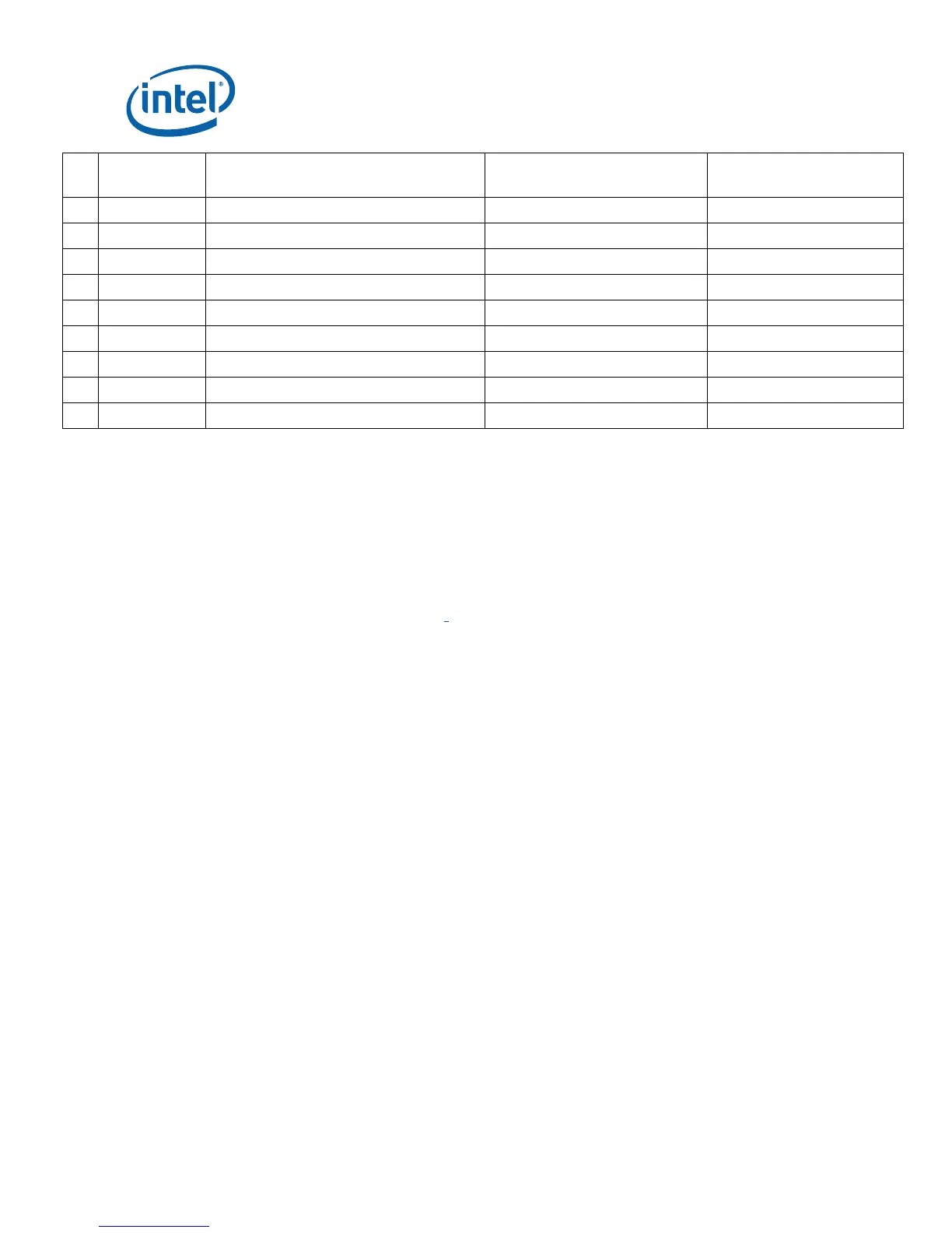
#
Reference
Designator Description
Default
Setting
Optional
Setting
26 J8H1 Boot BIOS Strap 1-2 1-X PCI to LPC
27 J9C1 PROGRAMMING SPI1 1-X 1-2 Program SPI-0
28 J9D1 PROGRAMMING SPI0 1-X 1-2 Program SPI-1
29 J9F1 KSC Enable 1-2 1-X
30 J9G2 Boot Block Programming 1-2 (Normal Operation) 1-X to Program the H8
31 J9H1 NMI 1-X 1-2 Disabled
32 J9H2 SATA interlock switch for port1 1-2 (Present) 1-X Disabled
33 J9H3 LID Position 1-X 1-2
34 J9H4 Virtual Battery 1-X 1-2
Note: A jumper consists of two or more pins mounted on the motherboard. When a jumper
cap is placed over two pins, it is designated as 1-2. When there are more than two
pins on the jumper, the pins to be shorted are indicated as 1-2 (to short pin 1 to pin
2), or 2-3 (to short pin 2 to pin 3). When no jumper cap is to be placed on the
jumper, it is designated as 1-X.
4.3.2 BSEL Jumper Settings
The jumper settings in Table 19 are provided to accommodate frequency selection for
the processor Power On and Reset Push Buttons.