Development Board Features
Development Kit User’s Manual 41
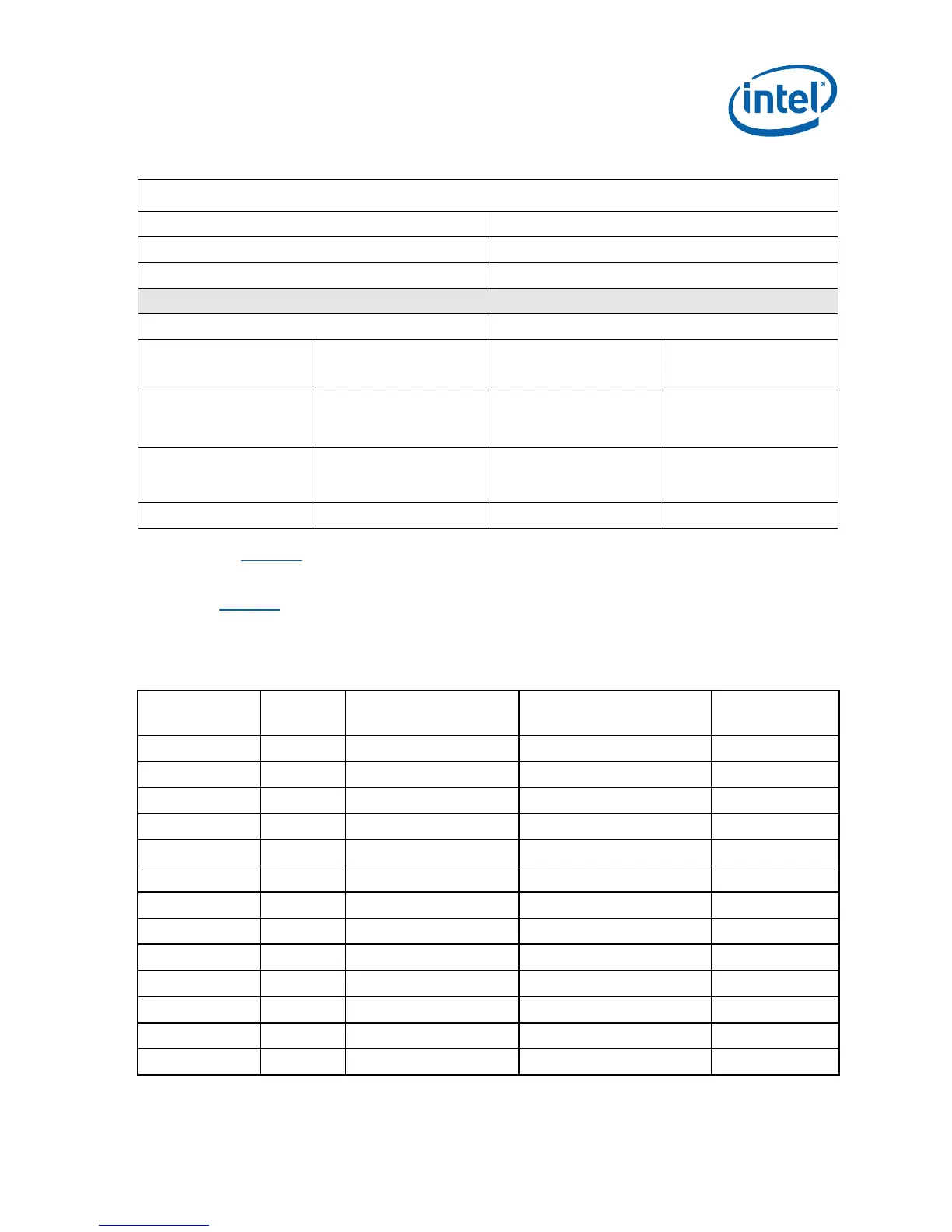
Table 14. Digital Multi-Meter Comparison
Example System
Sense Resistor Value: 0.002Ω
Voltage Difference Across Resistor: 1.492 mV (746 mA)
Calculated Power: 1.113 mW
Agilent 34401A (6 ½ digit display) Fluke 79 (3 digit display)
Specification: (±0.0030% of reading)
+ (±0.0030% of range)
Specification: ±0.09% ±2 digits
Min Voltage Displayed:
Calculated Power:
1.49193 mV
1.1129 mW
Min Voltage Displayed:
Calculated Power:
1.47 mV
1.08 mW
Max Voltage Displayed:
Calculated Power:
1.49206 mV
1.1131 mW
Max Voltage Displayed:
Calculated Power:
1.51 mV
1.14 mW
Error in Power: ±0.009% Error in Power: ±0.3%
As 2Table 14 shows the precision achieved by using a high precision digital multi-meter
versus a standard digital multi-meter is ~33 times more accurate.
2Table 15 summarizes all the power measurement sense resistors located on the
board. All sense resistors are 0.002Ω unless otherwise noted. Reference designators
marked with an asterisk are “not stuffed” on the board.
Table 15. System Voltage Rails
Component /
Interface
Voltage
Plane
Supply Rail Reference
Designator
CPU VR 5V +V5S +V5S_Intel® MVP6 R1B4
CPU VR Battery +VBAT +VDC_PHASE R1P6
CPU VR 1.05V 6262_PHASE1 +VCC_CORE R3D1
CPU VR 1.05V 6262_PHASE2 +VCC_CORE R2D1
CPU 1.05V +V1.05S +V1.05S_CPU R3U2* & R3U1*
CPU 1.5V +V1.5S +VCCA_PROC R3R14 (0.01Ω)
GMCH VR Battery +VBATA 1.05S_VIN R4G3
GMCH VR Battery +VBATA 1.05M_VIN R4V10
GMCH VR Battery +VBATA 1.5S_VIN R5V5
GMCH VR Battery +VBAT GVR_VBAT R3V1
GMCH VR 5 V +V5S +V5S_GVR R3F4
GMCH VR 3.3V +V3.3S_TVDAC +V3.3S_A_TV_DAC R4F3
GMCH VR 1.05 V 51124_LL2_L +V1.05M R4F7