EasyManua.ls Logo

Intel Core 2 Duo Processor User Manual

Intel Core 2 Duo Processor
81 pages
To Next Page IconTo Next Page
To Previous Page IconTo Previous Page
Page #39 background image
Development Board Features
Development Kit User’s Manual 39
3.6.26 Debug Interfaces
An XDP (Extended Debug Port) connector is provided at J1F1 for processor run control
debug support. This connector is compatible with both XDP and ITP-700. An external
adapter is used to interface ITPFlex700 cable to the platform. XDP incorporates new
run-control features on the JTAG interface and allows the user to communicate with
the processor or GMCH.
A port 80-83 display add-in card can also be used for debug. The port 80-83 add in
card could be used on the TPM header located at J9A1
Note: The XDP interface is backwards compatible with the ITP interface. However, an XDP to
ITP converter cable is necessary to use the older ITP tools. Also, in some cases a
resistor change rework is necessary to get the older ITP tools to function properly.
Please contact an Intel representative for additional details.
3.6.27 Board Form-Factor
The reference board form factor is similar to the full-size ATX specification and uses
10 layer board – 12” x 10.2”.
3.7 Power Management
3.7.1 Power Management States
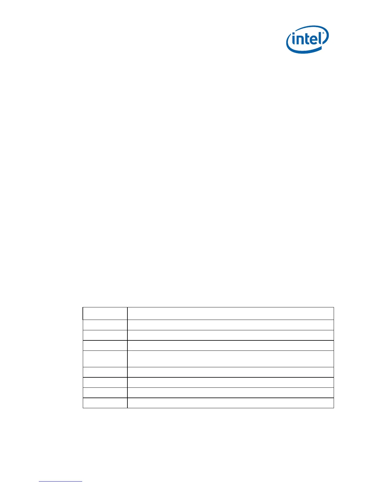
Table 12 and Table 13 list the power management states that have been defined for
the development board. The system’s Controller Link (CL) operates at various power
level, called the M-states. M0 is the highest power state, followed by M1 and M-off.
Table 12. System Power Management States
State Description
G0/S0/C0 Full on
G0/S0/C2 Quick Start: STPCLK# signal active
G0/S0/C3 Deep Sleep: CPUSTP# signal active
G0/S0/C4-C6 Deeper Sleep: Voltage to processor core is lowered (feature enabled by
software)
G1/S3 Suspend To RAM (all switched rails are turned off)
G1/S4 Suspend To Disk
G2/S5 Soft Off
G3 Mechanical Off

Table of Contents

Question and Answer IconNeed help?

Do you have a question about the Intel Core 2 Duo Processor and is the answer not in the manual?

Intel Core 2 Duo Processor Specifications

General IconGeneral
Number of Cores2
Manufacturing Process65nm or 45nm (depending on model)
Execute Disable BitYes
Enhanced Intel SpeedStep TechnologyYes
L2 Cache2MB, 4MB, or 6MB (depending on model)
Front Side Bus1066 MHz
Thermal Design Power (TDP)35W - 65W (depending on model)
Socket TypeLGA775
Clock Speed1.6 GHz - 3.33 GHz (depending on model)
Instruction Setx86, x86-64
Virtualization TechnologyYes (depending on model)
ArchitectureIntel Core Microarchitecture

Summary

Introduction

Content Overview

Manual overview, conventions, and support information.

Text Conventions

Explains notations, symbols, and abbreviations used in the document.

Glossary of Terms and Acronyms

Defines key terms and acronyms for enhanced clarity.

Development Kit Technical Support

Information on obtaining technical assistance and product support.

Related Documents

Lists related Intel documentation for further study.

Getting Started

Development Kit Contents

Lists hardware, software, and documentation included in the kit.

Workspace Preparation

Safety precautions for setting up the workspace.

System Setup and Power-Up

Step-by-step guide for board setup and power-on.

System BIOS

Information on BIOS features, configuration, and programming.

Development Board Features

Block Diagram

Visual overview of the board's architecture and connections.

Development Board Key Features

Summary of the board's main hardware capabilities.

System Features and Operation

Detailed view of system features and their operation.

Power Supply Usage and Recommendation

Guidance on compatible power supplies and usage.

Development Board Physical Reference

Board Components

Figure and descriptions of major board components.

Connectors

Description of board connectors and usage warnings.

Configuration Settings

Overview of adjustable settings via jumpers and switches.

Appendix A Add-In Cards

Port 80-83 Add-in Card (Included)

Description of the Port 80-83 diagnostic card.

Rework to Change Eaglemont Card from HDMI to Display Port

Instructions for modifying Eaglemont card.

Appendix B Rework Instructions

Internal HDMI Enabling

Steps to enable internal HDMI functionality.

Enabling the Integrated Trusted Platform Module (iTPM)

Procedures to enable the integrated TPM.

Enabling External HDMI

Configuration steps for external HDMI codec.

Low Voltage High-Definition (HD) Audio Rework

Steps to enable Low Voltage HD Audio.

Appendix C Programming System BIOS Using a Flash Programming Device

Appendix D CPU Thermal Solution (Heatsink) Installation

Related product manuals