EasyManuals Logo

Intel Core 2 Duo Processor User Manual

Intel Core 2 Duo Processor
81 pages
To Next Page IconTo Next Page
To Previous Page IconTo Previous Page
Page #61 background imageLoading...
Page #61 background image
Add-In Cards
Development Kit User’s Manual 61
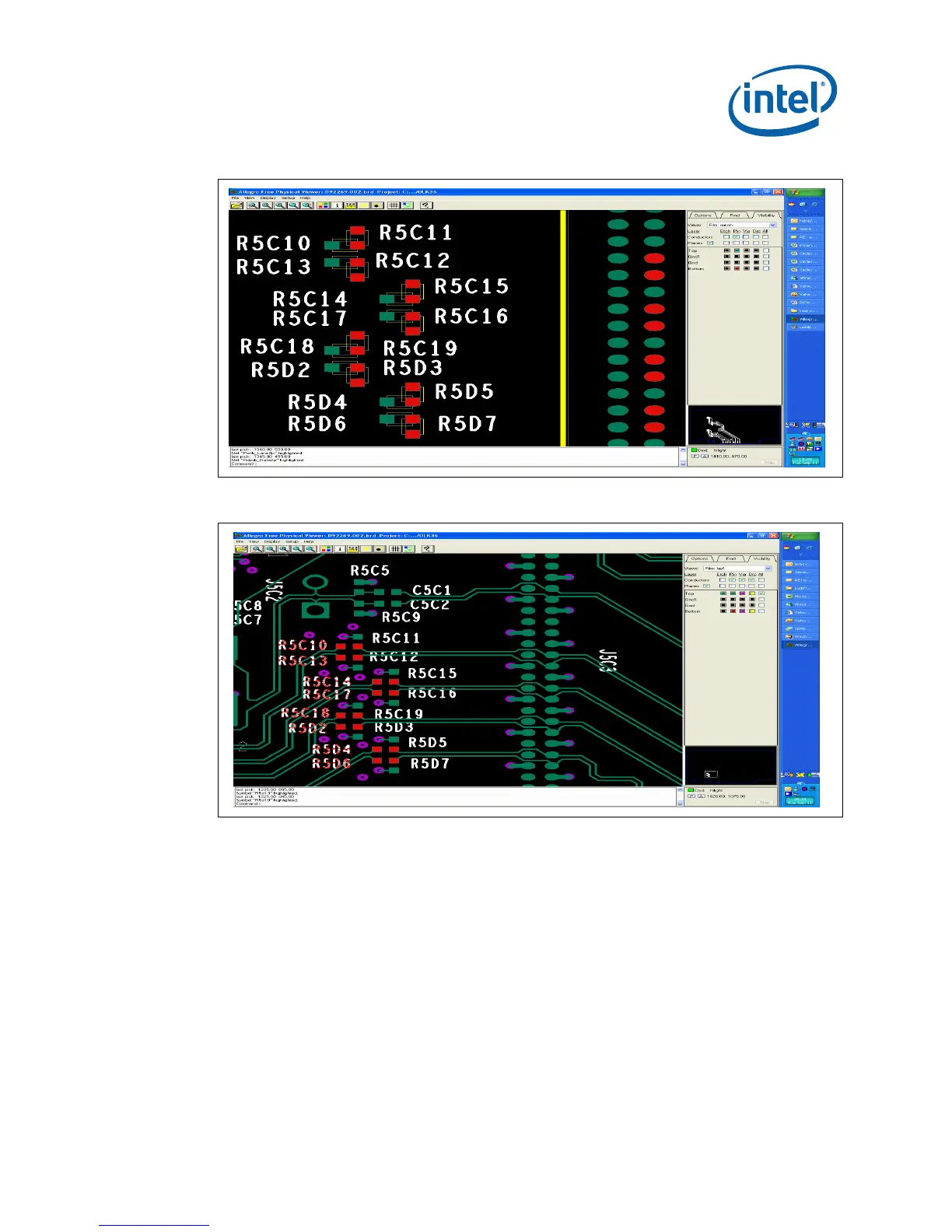
Figure 13. Location of Resistors for Rework (before Rework)
Figure 14. Location of Resistors for Rework (after Rework)
2. On the mid/upper left hand section of Eaglemont card, resistor locations
R5B22, R5B19, R5B18, R5B16, R5B14, R5B11, R5B9, and R5B6 can be
identified. As mentioned in the procedure above these resistors needs to be
taken off and assemble them in the ref. des. R5B21, R5B20, R5B17, R5B15,
R5B13, R5B10, R5B8, and R5B7. Refer the pictures below for resistor location
before and after rework. As mentioned in the procedure above, the vertically
mounted resistors need to be removed and assembled horizontally on
designated pads.

Table of Contents

Questions and Answers:

Question and Answer IconNeed help?

Do you have a question about the Intel Core 2 Duo Processor and is the answer not in the manual?

Intel Core 2 Duo Processor Specifications

General IconGeneral
Number of Cores2
Manufacturing Process65nm or 45nm (depending on model)
Execute Disable BitYes
Enhanced Intel SpeedStep TechnologyYes
L2 Cache2MB, 4MB, or 6MB (depending on model)
Front Side Bus1066 MHz
Thermal Design Power (TDP)35W - 65W (depending on model)
Socket TypeLGA775
Clock Speed1.6 GHz - 3.33 GHz (depending on model)
Instruction Setx86, x86-64
Virtualization TechnologyYes (depending on model)
ArchitectureIntel Core Microarchitecture

Related product manuals