Introduction
10 Development Kit User’s Manual
Notation Definition
Signal Names Signal names are shown in uppercase. When several signals share a
common name, an individual signal is represented by the signal name
followed by a number, while the group is represented by the signal name
followed by a variable (n). For example, the lower chip-select signals are
named CS0#, CS1#, CS2#, and so on; they are collectively called CSn#.
A pound symbol (#) appended to a signal name identifies an active-low
signal. Port pins are represented by the port abbreviation, a period, and
the pin number (e.g., P1.0).
1.3 Glossary of Terms and Acronyms
Table 2 defines terms used in this document.
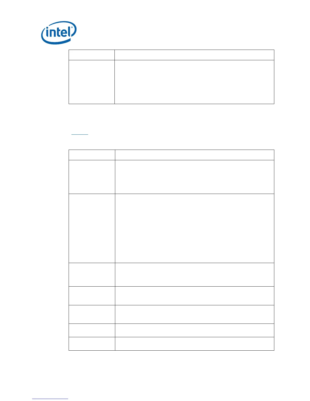
Table 2. Definitions of Terms
Term/Acronym Definition
Assisted Gunning
Transceiver Logic+
The front-side bus uses a bus technology called AGTL+, or Assisted
Gunning Transceiver Logic. AGTL+ buffers are open-drain, and require
pull-up resistors to provide the high logic level and termination. AGTL+
output buffers differ from GTL+ buffers with the addition of an active
pMOS pull-up transistor to assist the pull-up resistors during the first clock
of a low-to-high voltage transition.
Asynchronous
GTL+
The processor does not utilize CMOS voltage levels on any signals that
connect to the processor. As a result, legacy input signals such as A20M#,
IGNNE#, INIT#, LINT0/INTR, LINT1/NMI, PWRGOOD, SMI#, SLP#, and
STPCLK# utilize GTL+ input buffers. Legacy output signals (FERR# and
IERR#) and non-AGTL+ signals (THERMTRIP# and PROCHOT#) also
utilize GTL+ output buffers. All of these signals follow the same DC
requirements as AGTL+ signals, however the outputs are not actively
driven high (during a logical 0 to 1 transition) by the processor (the major
difference between GTL+ and AGTL+). These signals do not have setup or
hold time specifications in relation to BCLK[1:0], and are therefore
referred to as “Asynchronous GTL+ Signals”. However, all of the
Asynchronous GTL+ signals are required to be asserted for at least two
BCLKs in order for the processor to recognize them.
Infrared Data
Assoc.
The Infrared Data Association (IrDA) has outlined a specification for serial
communication between two devices via a bi-directional infrared data
port. The development board has such a port and it is located on the rear
of the board between the two USB connectors.
IMVP6+ The Intel Mobile Voltage Positioning specification for the Intel® Core™ 2
Duo Processor. It is a DC-DC converter module that supplies the required
voltage and current to a single processor.
Media Expansion
Card
The Media Expansion Card (MEC) provides digital display options through
the SDVO interface. The MEC card also incorporates video-in via a x1 PCI
Express* port.
Pad The electrical contact point of a semiconductor die to the package
substrate. A pad is only observable in simulations.
Pillar Rock The name of the development board in this development kit that uses
DDR2 SDRAM