USER MANUAL
INTEL® FALCON™ 8+ UAS
© 2017 Intel Corporation. All rights reserved 45
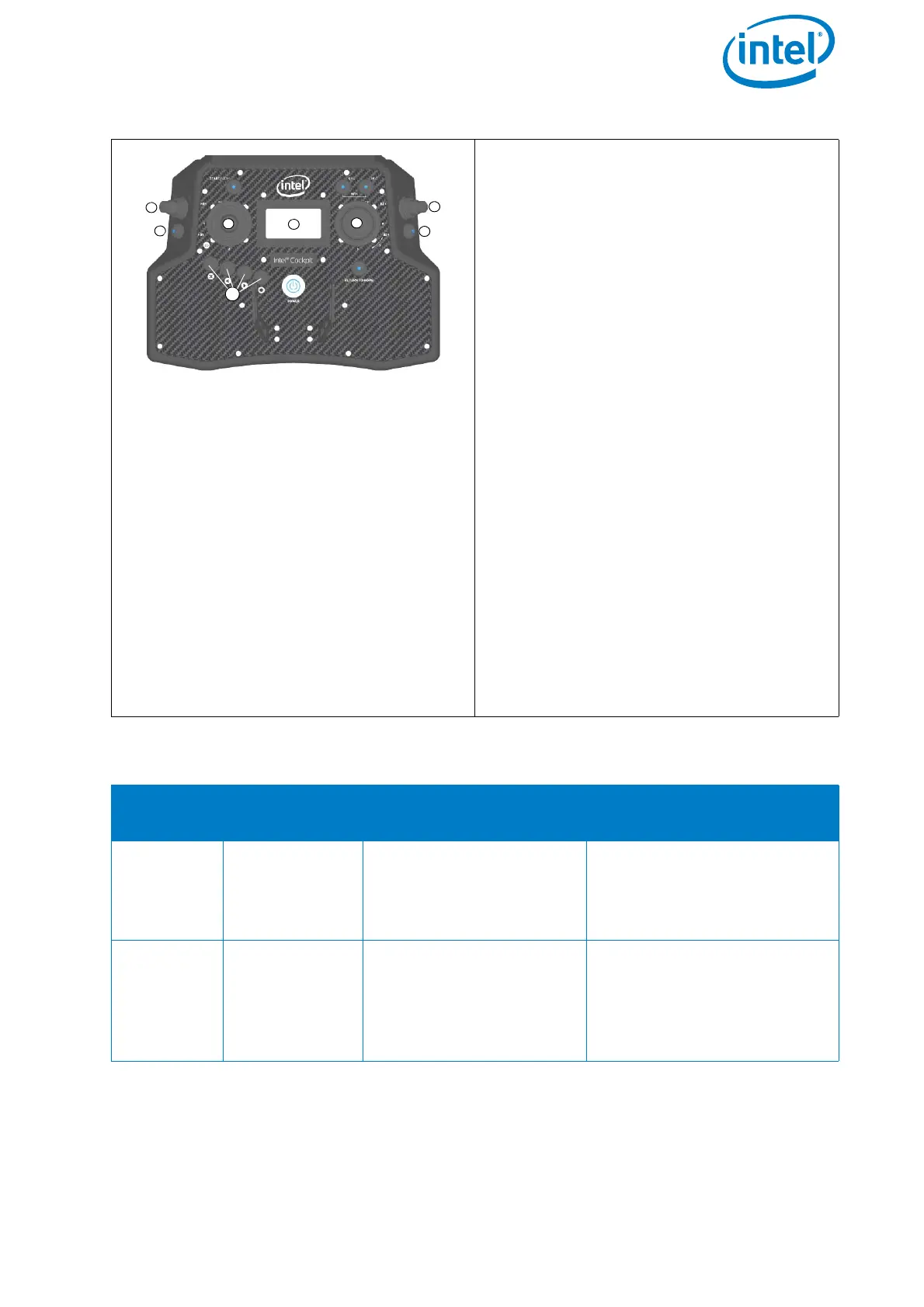
Push Button B1 (1): sets the camera to
predefined angles +/-90°, +/-45° and 0°
Push Button B2 (2): Switches between
the cameras for live preview (FLIR and
Panasonic)
Push Button B3 (3): Trigger button. Both
cameras will be triggered simultane-
ously, regardless of which camera is
selected for the live preview.
Rocker Switch R1 (4): camera tilt
Rocker Switch R2 (5): Changes its func-
tion depending which camera is selected
for live preview. See the table below for
details.
Control Stick S2 (6): turning the right
control stick (S2) controls the yaw axis of
the UAV
Status Display (7): see “Inspection Pay-
load Control By The Status Display” on
page 46.
ESC, LEFT, RIGHT, ENT (8): Status Dis-
play control buttons. (see “Status Dis-
play” on page 27). The table below
shows the available parameters depend-
ing on the shooting mode of the camera.
Table 2.1: Inspection Payload: CTR Control Layout
B2
POSITION
ACTIVATED
CAMERA
R2 FUNCTION
1 (LED off)
Panasonic
camera
Zoom in/out
Parameters like shutter
speed, aperture and ISO
need to be set directly on
the camera before take-off.
2 (LED on/
red)
FLIR
Up - Trigger flat field
correction
Down - Cycle through
color palette
Parameters like isotherms
and ACG need to be set via
configuration file on the
FLIR SD card before take-
off.
Figure 2.19: Inspection Payload: CTR Control Layout (Continued)