Intel® Server System M50CYP1UR Family System Integration and Service Guide
20
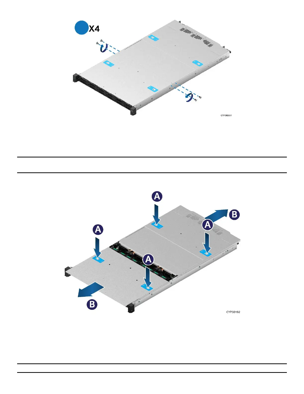
Figure 2. System Top Cover Panel Shipping Screws
The system ships from the factory with the front system cover panel and back system cover panel screwed
to the chassis. A total of four screws, one on each side of the front panel and one on each side of the back
panel, need to be removed to detach both top cover panels from the chassis.
Note: A non-skid surface or a stop behind the server system may be needed to prevent the server system
from sliding on the work surface.
Figure 3. System Cover Removal
For each top cover panel:
1. While pushing down on both the left and right buttons of the given top panel (see Letter A), slide the top
cover panel towards the front (front panel) or back (back panel) of the chassis (see Letter B).
2. Carefully lift the top cover panel up and away from the chassis.
Note: Each top cover panel can slide along the chassis base for 10 mm and then needs to be lifted.
 Loading...


