Intel® Server System M50CYP1UR Family System Integration and Service Guide
92
6.9 Server Board Replacement
Required Tools and Supplies
• Anti-static wrist strap and conductive workbench pad (recommended)
• Phillips* head screwdriver #2
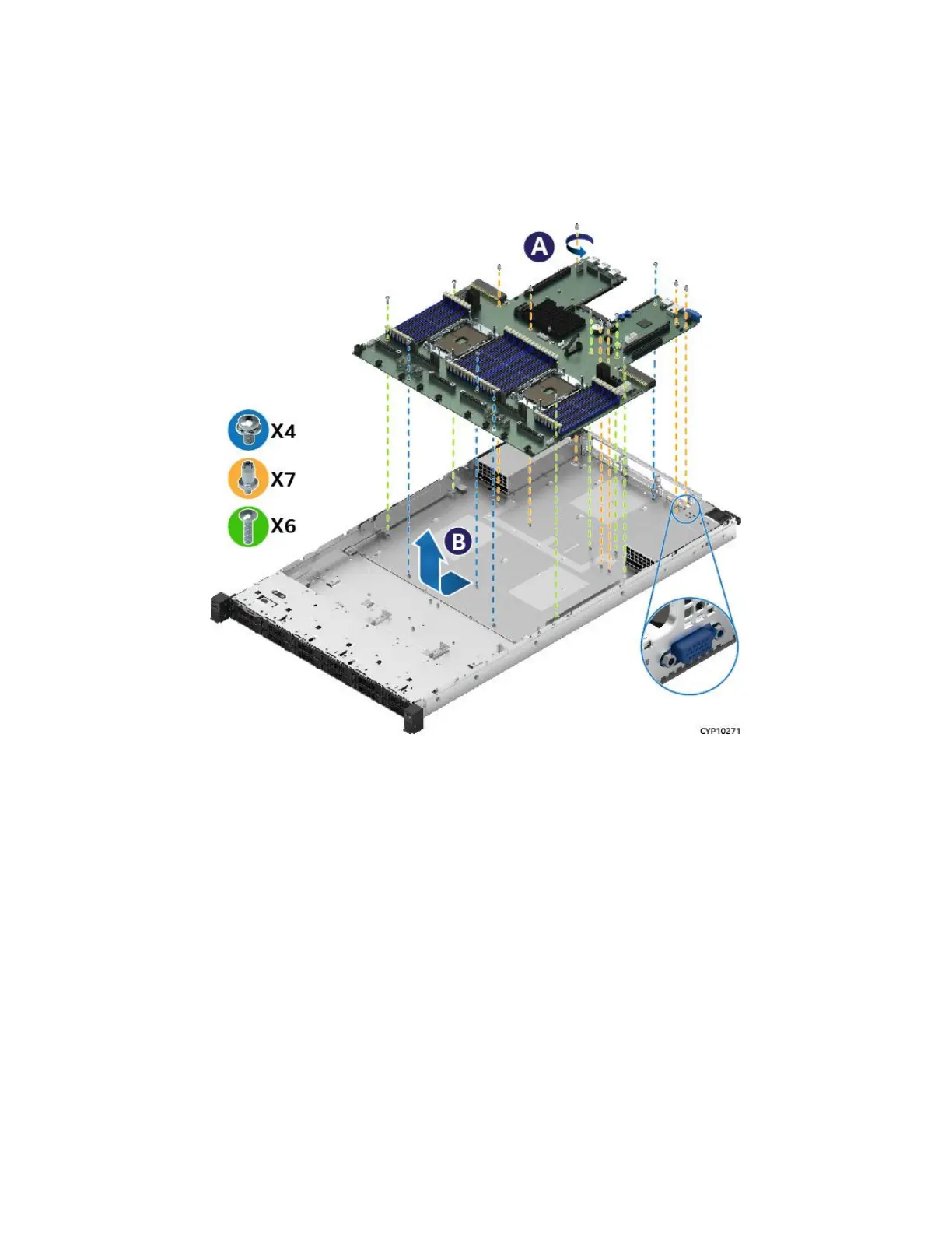
Figure 111. Server Board Removal
1. Power off system and remove power cords from each power supply module installed.
2. Disconnect all externally attached cables.
3. Remove the system top cover (see Section 6.1.1).
4. Remove power supply modules (see Section 6.4).
5. Remove individual system fan (see Section 6.2).
6. Disconnect all cables attached to add-in cards and I/O modules.
7. Remove riser card assemblies (see Section 3.2.1).
8. Remove all options installed onto the server board including (if installed): TPM Module, M.2 SSD, Intel®
VROC 7.5 key, OCP* adapter, Intel® SAS interposer card and SAS RAID module.
9. Remove processors (see Section 6.5).
10. Remove all DIMMs (see Section 6.3).
11. Disconnect and clear from the server board area all cables attached to connectors on the server board.
12. Remove 17 screws used to secure the server board to the chassis (see Letter ‘A’).
13. Slide the server board slightly towards the front of the chassis to disengage from the chassis cut-outs the
connectors on the rear edge of the board.
14. Carefully lift the server board from the chassis and place it into an anti-static bag.
 Loading...


