Intel® Server System M50CYP1UR Family System Integration and Service Guide
49
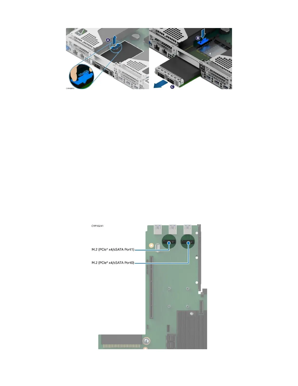
3.4.7 OCP* Adapter with Internal Lock Removal
Figure 48. OCP* Adapter with Internal Lock Removal
1. Remove the system top cover (see Section 3.1.1).
2. Remove any riser card assembly above the OCP* adapter area if present (see Section 3.2.1).
3. Squeeze the two hooks of the internal lock and pull it out (see Letter A).
4. Install it back in the chassis in reverse orientation (see Letter B).
5. Push the OCP* adapter out of the bay from inside the chassis (see Letter C).
6. Reinstall the riser card assembly as needed (see Section 3.2.4).
7. Reinstall the system top cover (see Section 3.1.2).
3.5 M.2 Storage Device Installation / Removal
The server board includes two M.2 connectors as shown in the following figure. Each M.2 connector supports
a PCIe* NVMe* or SATA SSD drive that conforms to a 22110 (110 mm) or 2280 (80 mm) form factor.
Required Tools and Supplies
• Anti-static wrist strap and conductive workbench pad (recommended)
• Phillips* head screwdriver #1
Figure 49. M.2 SSD Connector Location
 Loading...


